background image

11

Operation

G e t t i n g   S t a r t e d

1.

Set up the controller and lights as described in sections 2 and 3. 

2.

Slide the faders to 0.

3.

Apply power to the lights. Some fixtures must be turned on before the
controller is turned on in order to automatically detect the control proto-
col. After a short reset procedure, the lights will be ready to respond to
the controller.

4.

Apply power to the 2518 DMX Controller.

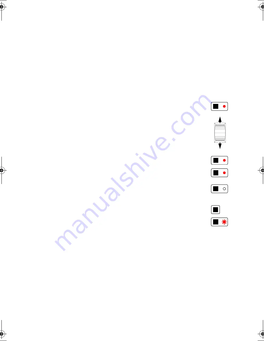
S e t t i n g   L i g h t s

1.

Activate fader control of channels between 1 and
36:
 Press a channel button to activate control. 

2.

Control the effects: Slide the faders up and
down to control the effects. If there is no light from
the fixture, set all effects to the open position and
turn on the lamp, if applicable, using the fixture’s
DMX protocol as your guide.

3.

You may activate fader control on more than one
button if you want to control several fixtures with
the same protocol. This only works if their start
channels map to the same fader. 

4.

Deactivate fader control: Press the button again
to turn off fader control. The LED goes out to indi-
cate manual control is turned off. 

5.

Activate fader control of channels between 37
and 72:
 Press the channel master to switch con-
trol between channels 1 - 36 and 37 - 72. Press a
channel button to activate control of the second
group of channels. 

P r o g r a m m i n g   S c e n e s

A light show is made up of scenes. A scene is a complete set of DMX values for each fix-
ture. It contains control instructions for all programmable effects for each device. In addi-
tion, a scene may contain speed information. For example, some lights have dimmers that
may be set to fade slowly or snap instantly.

Scenes are programmed by setting the lights as described above and then saving the settings
in memory. 

Six scenes can be stored in each bank. The 2518 DMX Controller has 30 banks; up to 180
scenes may be programmed and saved in its memory. 

1-6

(37-42)

13-18

(49-54)

19-24

(55-60)

1-6

(37-42)

1-6

(37-42)

1-36

(37-72)

2518 IV.BOOK  Page 11  Tuesday, September 22, 1998  7:10 PM

Summary of Contents for DMX Controller 2518

Page 1: ...2518 DMX Controller user manual P N 510158...

Page 2: ...ssional A S Denmark All rights reserved No part of this manual may be reproduced in any form or by any means without permission in writing from Martin Professional A S Denmark Printed in Denmark P N 5...

Page 3: ...3 2518 DMX Controller...

Page 4: ...nnecting a MIDI Device 6 Connecting to the Power Supply 6 section 3 Address and Mode Setting About Addresses and Modes 7 Setting an Address 8 section 4 Operation Manual Control 10 Programming Scenes 1...

Page 5: ...ediately repair or replace damaged power cords There are no user serviceable parts inside refer all service to a qualified technician F eatu re s 72 DMX channels 30 banks of 6 programmable scenes 6 fa...

Page 6: ...nnecting the output of the fixture closest to the controller to the input of the next fixture Connecting outputs to inputs is complicated a little by the fact that the connection sockets are not alway...

Page 7: ...evice with DMX pin out to a device with Martin pin out you must use a phase reversing cable that swaps the connections between pins 2 and 3 Output Input Polarity Martin pin 2 pin 3 DMX pin 2 pin 3 XLR...

Page 8: ...tin DMX Switch Pack each count as 1device 5 Always terminate the link Terminate the link by installing the provided termination plug in the output socket of the last fixture on the link The terminatio...

Page 9: ...o 15 meters 50 feet long Connecting to t he Power Supply W A R N I N G For safe operation the controller must be grounded earthed In s ta ll P lu g The 2518 DMX Controller is delivered without a plug...

Page 10: ...ctor mode speed is programmed on 1 or 2 additional channels Devices may be controlled in tracking mode if there are not enough channels but speed control will not be possible Controlling a light is ea...

Page 11: ...dependently so 2 RoboColor Pro 400s are together on channels 44 48 and 2 more are together on channels 56 60 They are set for 5 channel tracking mode because there is not enough room for 7 channel vec...

Page 12: ...mode speed control of these units will not be possible Button 1 Button 2 Button 3 Button 4 Button 5 Button 6 Ch Device Ch Device Ch Device Ch Device Ch Device Ch Device 1 36 1 RoboColor IIx 7 RoboColo...

Page 13: ...hannels from 1 to 36 are active a flashing LED indicates channels from 37 to 72 are active Status is indicated for 36 channels at a time press the channel master to see the status of the other channel...

Page 14: ...the same protocol This only works if their start channels map to the same fader 4 Deactivate fader control Press the button again to turn off fader control The LED goes out to indi cate manual contro...

Page 15: ...desired changes 3 Save the edited scene as described above Co py in g a S c e ne If you want to use the settings from one scene as the starting point for another scene you may copy the scene and edit...

Page 16: ...ach scene MIDI scenes can also be used to switch banks When a MIDI scene is executed the active bank automatically changes to the bank where the scene is stored If you have several MIDI devices MIDI r...

Page 17: ...scene in the active bank starting at scene 1 After scene 6 the next trigger pulse executes scene 1 again Scenes may also be executed manually in any order by pressing the scene buttons Ch a ngi ng Ba...

Page 18: ...a M ID I Tr igg e r Note A MIDI code may be used either as a trigger or to execute a MIDI scene but not both 1 Press Midi The display flashes 2 Press Auto 3 Optional Select a MIDI channel Press the u...

Page 19: ...n standby mode there is no DMX output from the controller Standby mode uses less current and is recommended whenever the controller is not being used for more than a few minutes to reduce wear and tea...

Page 20: ...tures do not respond respond erratically or continuously reset Bad data link connection Check data link connections cables and correct accord ingly DMX signal polarity reversed Swap pins 2 and 3 See s...

Page 21: ...nd 6 at the same time while applying power to the controller The channel LEDs chase upwards 3 Slide the 6 faders all the way up to the top 4 Press a DMX Channel button 5 To verify calibration slide ea...

Page 22: ...0 Hz US model 100 to 130 V 50 to 60 Hz Prog ra m mi ng C a pa c i ty Scenes 180 MIDI triggers 2048 DM X C a pa c ity 72 channels Tr i gg er S ou rc es adjustable timer MIDI internal microphone Re a r...

Reviews: