Copyright © 2019 Martin Audio Ltd.
28
WPL USER GUIDE V1.0
WPL USER GUIDE
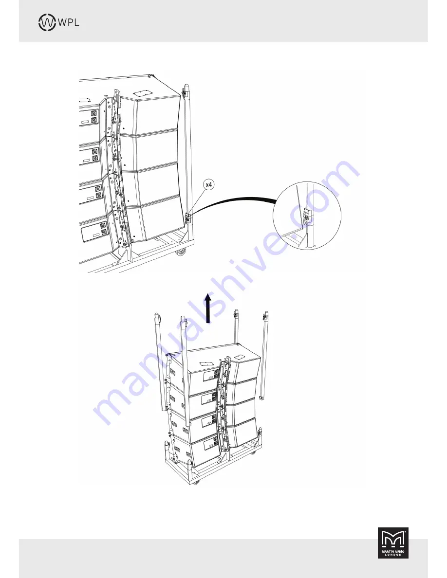
Unlatch the supporting poles (fig. 29) from the transport cart tray and lift them off (fig. 30).
fig. 29
fig. 30
Page 1: ...User Guide WPL Optimised Line Array...
Page 2: ...Wavefront Precision Longbow 5 Mechanical Design 5 Acoustic Design 5 Acessories SXH218 Subwoofer 6 iK42 Amplifier 6 DISPLAY 2 3 Overview 7 VU NET 2 2 Overview 11 Rigging WPL Overview 15 WPL Connections...
Page 3: ...athway into the world of advanced optimisation The greater the resolution of the array in terms of individually driven enclosures the more precisely DISPLAY can fine tune audience coverage and hold th...
Page 4: ...re specified by Martin Audio When moving using supplied wheelboards caution should be used to avoid injury from the cabinet tipping over Unplug this apparatus during lightning storms or when unused fo...
Page 5: ...to a 8 000 seat venue saving on truck space and weight Mechanical Design WPL is designed mechanically to be an easy to handle quick to rig safe rugged and stable touring loudspeaker The cabinet is con...
Page 6: ...ontrol for WPL systems The iK42 can deliver a full 5000 watts per channel into 2 ohms with all channels driven while remaining highly efficient Its high efficiency reduces the energy drawn from the ma...
Page 7: ...traightforward to use taking you through a series of steps in a logical order In fact it won t allow you to attempt to design a system in the wrong order steps need to be completed one after the other...
Page 8: ...art to finish The coverage tab shows your 2D model with the planes refined into three types audience in green non audience in red and hard avoid in blue Each dot represents a virtual microphone positi...
Page 9: ...ied hole in the frame will give will be displayed with the option to use this angle in the optimisation so that the array EQ is optimised for the actual physical position in which the array is install...
Page 10: ...the 2D slice of the venue top left whilst showing the frequency response at that position on the graph on the right The final stage is to export your design You can produce a printable rigging report...
Page 11: ...IP configuration is also easily enabled VU NET is used to upload the presets created using DISPLAY 2 3 into the amplifiers which will automatically create a thumbnail of the Wavefront Precision array...
Page 12: ...9 Martin Audio Ltd 12 WPL USER GUIDE V1 0 WPL USER GUIDE The next stage is to right click on the amplifiers to access the Preset Manager From here the system allows you up upload the D2P file of your...
Page 13: ...application perhaps adding some delay to align subwoofers Input EQ can be adjusted to suit your preferences and to compensate for any difficult acoustics The output EQ is greyed out as it is used to a...
Page 14: ...plex system allowing you to monitor all metering and access commonly needed functions such as gain and mute VU NET is a free download from the software page of the Martin Audio website at www martin a...
Page 15: ...rigging points at the front and a single rigging point at the rear of the cabinet The rear rigging bracket assembly fig 3 provides eight rigging holes allowing for inter cabinet angles of 0 5 1 2 3 4...
Page 16: ...or link output Since WPL is a bi amped system all speaker cables and link cables must utilise 4 core cable When the system is configured for a single box resolution system each cabinet is connected to...
Page 17: ...o meet BGVC1 allowing both positive up tilt and negative down tilt array tilt angles A two part inclinometer is available for use with the touring flying frame which displays the angle at which the WP...
Page 18: ...V1 0 WPL USER GUIDE Transport Cart for WPL An optional dedicated transport cart is available to house an array of four WPL cabinets This will allow safe transportation and convenient rigging and de ri...
Page 19: ...L array and the flying frame when the system is configured for ground stacking Depending on where the ground stack bar is attached to the touring flying frame a range of aiming angles from 4 to 10 can...
Page 20: ...Once coupled with the ASM20019 inclinometer read out display via a standard 3 pin XLR mic cable precise measurements of the angle of the array can be taken to ensure that the DISPLAY optimisation is...
Page 21: ...cap head screws supplied with the sensor These go through the holes in the bottom left and top right of the box into the threaded holes in the grid bracket Tighten using an M3 allen key to ensure a ti...
Page 22: ...se with the inclinometer system part number PWA00057 This is a 35m cable using high grade AES spec microphone cable fitted with male and female Neutrik NC3XX HD connectors which are extra rugged and h...
Page 23: ...d the outer diameter of the pin thus locking them in place To release them the central button is depressed fig 16 When using the pins to link cabinets the central button must again be depressed so the...
Page 24: ...PL USER GUIDE The front flying brackets are stored in the transit position and secured with rigging pins Remove the pin on each side and raise the rigging bracket fig 19 then secure in the raised posi...
Page 25: ...rop link bar with indexed holes which can be slid vertically upwards between the two constraining steel brackets fig 21 and secured with the rigging pins in one of several different positions fig 22 d...
Page 26: ...ble for rigging Rigging pins are inserted at the holes required for the cabinet angles as predicted by your DISPLAY 2 3 project The array is then lifted so that the angles open until the rear rigging...
Page 27: ...Copyright 2019 Martin Audio Ltd 27 WPL USER GUIDE V1 0 WPL USER GUIDE Unlatch the top from the supporting poles in four places fig 27 lift it off and set it aside fig 27 fig 27 fig 28...
Page 28: ...Copyright 2019 Martin Audio Ltd 28 WPL USER GUIDE V1 0 WPL USER GUIDE Unlatch the supporting poles fig 29 from the transport cart tray and lift them off fig 30 fig 29 fig 30...
Page 29: ...UIDE V1 0 WPL USER GUIDE With the supporting poles removed from the transport cart the inter cabinet angles should now be checked or if not already preselected set them now according to the prediction...
Page 30: ...Copyright 2019 Martin Audio Ltd 30 WPL USER GUIDE V1 0 WPL USER GUIDE Lift the front rigging brackets on the left and right of the top WPL in the cart fig 32 and pin in position fig 33 fig 32 fig 33...
Page 31: ...rigging position on each side fig 35 Place the WPLGRIDt flying frame on the top cabinet in either the front or rear position as determined by the DISPLAY 2 3 project fig 34 Most arrays will use the fr...
Page 32: ...rtin Audio Ltd 32 WPL USER GUIDE V1 0 WPL USER GUIDE Attach the drop link from the rear of the top cabinet to the flying frame at the LINK position fig 36 Insert a rigging pin at the LOCK position fig...
Page 33: ...Insert a further rigging pin at the LOCK position on each cabinet to lock the inter cabinet angles fig 38 At this stage the cable loom should be attached to the grid and the first four cabinets conne...
Page 34: ...tin Audio Ltd 34 WPL USER GUIDE V1 0 WPL USER GUIDE Repeat at the front of the array supporting the cart and removing the pins holding the cart to the array fig 40 fig 41 Lower the back of the cart to...
Page 35: ...WPL USER GUIDE Once the cart is removed the four supporting poles can be placed in the base fig 42 and the top fitted directly to the base and the two clipped together fig 43 The assembly can now be...
Page 36: ...WPL USER GUIDE Position a second loaded WPL transport cart underneath the array fig 45 remove the top and poles and prepare the cabinets to be added to the array Lift the array to a height where a sec...
Page 37: ...Copyright 2019 Martin Audio Ltd 37 WPL USER GUIDE V1 0 WPL USER GUIDE Unlatch the top from the supporting poles in four places fig 46 lift it off and set it aside fig 47 fig 46 fig 47...
Page 38: ...Copyright 2019 Martin Audio Ltd 38 WPL USER GUIDE V1 0 WPL USER GUIDE Unlatch the supporting poles from the transport cart tray fig 48 and lift them off fig 49 fig 48 fig 49...
Page 39: ...Audio Ltd 39 WPL USER GUIDE V1 0 WPL USER GUIDE Preselect the inter cabinet angles on the lower three cabinets according to the predictions from your DISPLAY 2 3 project fig 50 Remove the rigging pins...
Page 40: ...ign the front rigging points of the fourth cabinet with the front rigging points of the fifth cabinet fig 52 Raise the front rigging brackets on the fifth cabinet and insert a rigging pin on both side...
Page 41: ...2019 Martin Audio Ltd 41 WPL USER GUIDE V1 0 WPL USER GUIDE Insert the front rigging pins into the fifth cabinet fig 54 Lower the upper array fig 55 fig 54 fig 55 4th cabinet 5th cabinet 4th cabinet 5...
Page 42: ...Ltd 42 WPL USER GUIDE V1 0 WPL USER GUIDE Insert front rigging pins in the fifth cabinet fig 56 Raise the array clear of the transport cart allowing access to the rear of the array fig 57 fig 56 fig...
Page 43: ...as the pins will allow to the angle that has been pre selected Insert rigging pins at the LOCK position on the remaining cabinets fig 58 Swing the bottom four cabinets which will now be a rigid array...
Page 44: ...ing the cart to the array fig 61 Insert a pin in the rear rigging bracket at the correct angle Allow the bottom four cabinets to swing back down and insert rigging pins into the LINK and LOCK position...
Page 45: ...Audio Ltd 45 WPL USER GUIDE V1 0 WPL USER GUIDE Lower the back of the cart to the ground fig 62 Repeat at the front of the array supporting the cart and removing the pins holding the cart to the array...
Page 46: ...ray to the final trim height The use of either one or two motors allows both negative down tilt or positive up tilt array angles to be easily achieved fig 64 and 65 Stow the supporting poles in the tr...
Page 47: ...into a WPL transport cart unpinning the lower block of four and repeating with the top four cabinets Lower the array to a convenient working height Disconnect the speaker cables Position a WPL transpo...
Page 48: ...Copyright 2019 Martin Audio Ltd 48 WPL USER GUIDE V1 0 WPL USER GUIDE At the back of the array raise the cart fig 69 Pin the cart to the rear rigging bracket of the array fig 70 fig 69 fig 70...
Page 49: ...move the LOCK rigging pins from the rear rigging bracket on the bottom four cabinets fig 71 Lower the array until the cart is on the ground taking the weight of the array allowing the cabinets to coll...
Page 50: ...ER GUIDE Carefully unpin the fifth cabinet from the fourth cabinet at the rear by removing the LINK pin fig 73 be aware that the array may swing when this is done Lower the array down so that the cart...
Page 51: ...R GUIDE Remove the front rigging pins from the front of the fifth cabinet at each side fig 75 Ensure the cart is fully grounded when removing pins Lift the array a fraction so that there is no weight...
Page 52: ...ht 2019 Martin Audio Ltd 52 WPL USER GUIDE V1 0 WPL USER GUIDE Remove the front link pins fig 77 The front links will then drop down Lift the remaining array cabinets away from the cart fig 78 fig 77...
Page 53: ...t 2019 Martin Audio Ltd 53 WPL USER GUIDE V1 0 WPL USER GUIDE Replace the front rigging pins in into the cabinet fig 79 Replace the supporting poles and top into the base of the WPL cart fig 80 fig 79...
Page 54: ...19 Martin Audio Ltd 54 WPL USER GUIDE V1 0 WPL USER GUIDE Replace the lid of the WPL cart fig 81 Lower the remaining four cabinets and repeating the procedure above lowering the array into a transport...
Page 55: ...stacking first find a suitable safe flat surface and place the WPL flying frame in position Remove the pins securing the front flip up bars and swing the bars up until they are vertical fig 82 You ca...
Page 56: ...ons These fit into the slot vacated by the flip up bar If you have pinned the bar in the vertical position remove the pin hold the bar vertical and place the outrigger in position Replace the upper pi...
Page 57: ...rientation of the bar and the correct hole to use in the frame will be determined by the angle of the first WPL cabinet in the stack and will be calculated by the DISPLAY 2 3 project Remove the front...
Page 58: ...Martin Audio Ltd 58 WPL USER GUIDE V1 0 WPL USER GUIDE Insert rigging pins in the WPL front brackets fig 88 Remove the rigging pins in the upper front rigging brackets and raise the linking bar fig 89...
Page 59: ...DE Replace the rigging pins to hold the bars in the up position fig 90 Raise the rear of the WPL which will hinge on the front pins Swing the ground stack bar up until the upper hole is aligned with t...
Page 60: ...GUIDE V1 0 WPL USER GUIDE Insert a rigging pin in the lowest hole to secure the rear of the WPL fig 92 You now repeat the process for the second cabinet removing the front pins and lowering it onto th...
Page 61: ...s fig 94 Lift the rear flying bracket of the first cabinet and insert a rigging pin in the hole for the angle required as indicated in the DISPLAY project Lift the back of the second cabinet until the...
Page 62: ...Copyright 2019 Martin Audio Ltd 62 WPL USER GUIDE V1 0 WPL USER GUIDE Repeat the process adding cabinets to build the ground stack to the required number of WPL fig 96 fig 96...
Page 63: ...horizontal 6dB 120 horizontal 10dB 7 5 vertical CROSSOVER 320Hz active 4kHz internal passive ENCLOSURE Vertical trapezoid with 3 75 wall angle multi laminate birch and poplar ply construction FINISH...
Page 64: ...td in the United Kingdom United States and other countries all other Martin Audio trademarks are the property of Martin Audio Ltd Martin Audio Limited Century Point Halifax Road Cressex Business Park...