20
When the Tally Source is set to TSL/MEI 422, OSD Tally can be set to
Off
or
IMD
:
• Off
On-screen tally is disabled
• IMD
Red, yellow, and green tally is displayed according the protocol commands. Green, red, and yellow colors are
shown individually on either the bottom left or right of the screen.
■
LED Tally
Use this to enable or disable the physical LED tally on the top of the monitor.
■
Anc. Timecode
Use this setting to enable time code display on the screen. Time code is de-embedded from the vertical ancillary data (VANC)
within the HD/SDI signal. Two types of time code can be selected to display on the screen:
LTC (linear time code)
or
VITC
(vertical interval time code)
.
The position of the time code display varies based on the aspect ratio setting and presence of IMD text.
■
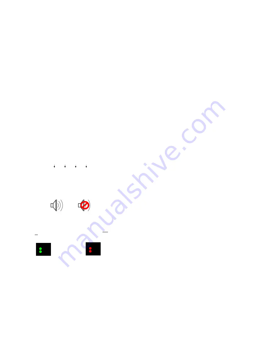
Audio Monitor
Use the Audio Monitor menu option to enable or disable the audio presence indicator icon. When enabled, this icon indicates
whether embedded audio is present in the HD/SDI video input. A red circle and cross will flash on the icon if no embedded
audio is present.
■
CC Monitor (Closed Captioning)
Use the CC Monitor menu option to enable or disable the Closed Captioning presence indicator icon. When enabled, this icon
indicates the presence of 608 and/or 708 embedded Closed Captioning in the SDI video input. A
green
dot indicates the
presence of CC Data. A
red
dot indicates no captioning data.
Embedded Audio Present
No Embedded Audio
No CC Data present
CC
608
708
Both 608 and 708 CC Data present
CC
608
708
00:00:00:00
Time Code display
Hours
Minutes
Seconds
Frames
17
■
User-Definable Function Buttons
Use the
Function 1
,
Function 2
,
Function 3 and Function 4
menu items to define each function button on the front panel of
the monitor. Alternatively, you can save a preset to either of the function buttons by holding down F1, F2, F3 or F4 for 5
seconds. The following options are available for each button:
• Marker
Toggle between different Screen Markers
• Center Marker
Display/hide the Center Marker
• Marker Enable
Display/hide on screen markers
• Marker Backgrd
Change how markers are displayed on the screen
• IMD State
Display/hide IMD text
• Anc. Time Code
Display/hide time code
• OSD Tally
Rotate amongst types of OSD Tally
• Audio Monitor
Display/hide audio presence indicator
• CC Monitor
Display/hide the Closed Caption Presence indicator
• Waveform Mode
Change the data displayed on the Waveform monitor
• Overlay Position
Change the position of the WFM Overlay in DLW Overlay Mode
• Limits
Toggle the Limits option of the Waveform Monitor On or Off
• User 1
Recall User settings in the User 1 configuration
• User 2
Recall User settings in the User 2 configuration
• User 3
Recall User settings in the User 3 configuration
• User 4
Recall User settings in the User 4 configuration
• User 5
Recall User settings in the User 5 configuration
• User 6
Recall User settings in the User 6 configuration
• Aspect Ratio
Toggle between 4:3 and 16:9 aspect ratios
• Pixel to Pixel
Enable/disable Pixel-to-Pixel mode
• Ctemp/GammaRotate amongst color temperature settings
• Blue Only
Enable/disable Blue Only mode
• Monochrome
Enable/disable Monochrome mode
■
Saving and Loading User Presets
Use the SAVE CONFIG and LOAD CONFIG menus to save current settings to one of 6 presets, or load a preset. Each Preset
saves all monitor settings except for IMD configuration. Alternatively, you can save a preset to either of the function buttons
by holding down F1, F2, F3 or F4 for 5 seconds.
•
Use the LOAD CONFIG menu to load one of presets USR1 – USR6. Factory default settings can also be loaded by
selecting MFG. (Factory defaults cannot be overwritten.)
•
Use To perform a full system restore, which resets ALL adjustable fields on the monitor to their “fresh-from-factory”
state, press the Power, F1 and F2 button simultaneously.
Note: You will lose ALL user adjustable settings on your
monitor.
•
Use the SAVE CONFIG menu to save the current settings to a preset from USR1- USR6.
■
Green, Red, Yellow GPI
Use the GPI settings to determine the function of a specific Tally pin on the back of the unit. The GPI Pin actions are toggled by
bringing the pin LOW. The Red, Green or Yellow Tally pins can activate a variety of settings, listed below.
•
Tally
Illuminate Green, Red or Yellow Tally LED
•
Monochrome
Enable/disable Monochrome mode
•
Blue Only
Enable/disable Blue Only mode
•
Pixel to Pixel
Enable/disable Pixel to Pixel mode
Summary of Contents for V-R185-DLW
Page 4: ...4 33...
Page 6: ...6 31 Dimensions...


