14
This mode bypasses the monitor’s internal scaling function and displays images in their native resolution and aspect ratio,
with a one-to-one mapping of incoming image pixels to screen pixels:
•
For incoming formats smaller than the native resolution of the window (or selected aspect ratio), the image will be
displayed in the center of the window using only the necessary LCD pixels. For example, 480i images will only occupy
exactly 640x480 pixels in a particular channel window in DLW mode, or if the channel is selected full screen, it will
occupy exactly 640x480 pixels in the center of the screen. The surrounding screen area will be black.
■
Aspect Ratio Settings
Use this menu option to switch between several aspect ratio settings.
As the V-R185-DLW monitor has a native resolution of 1366x768 RGB pixels, incoming images are automatically scaled to fit
the screen:
•
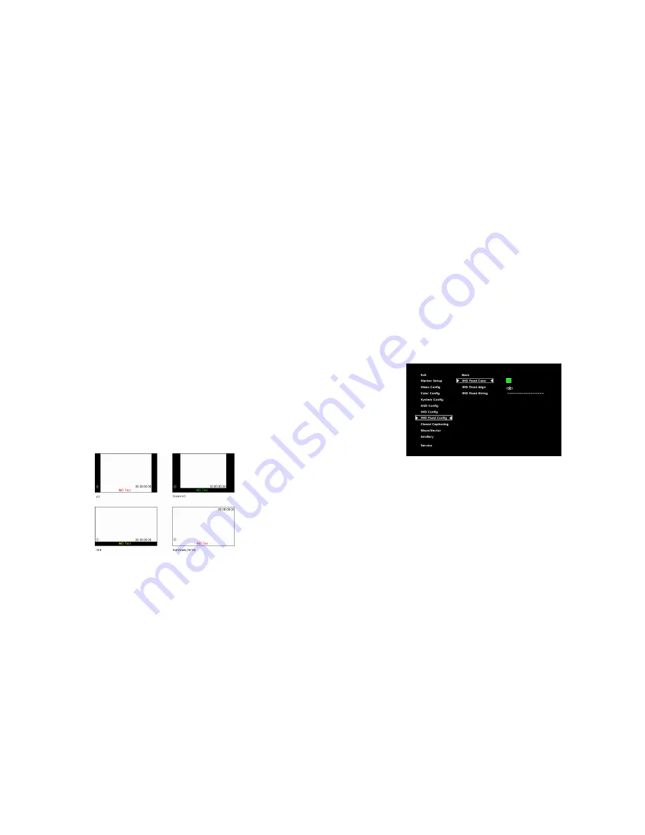
In
4:3
mode, images are scaled up or down to fill the maximum 4:3 portion of the screen. IMD text and time code are
superimposed on the lower portion of the image. The audio presence indicator and on-screen tally are displayed at the
bottom of the screen, outside the image.
•
In
Scaled 4:3
mode, images are scaled to a smaller 4:3 portion of the screen, leaving space for IMD text, tally, and audio
presence indicator to be displayed below or around the image. Time code is superimposed on the lower portion of the
image.
•
In
16:9
mode, images are scaled to fill the maximum 16:9 portion at the top of the screen. In this mode, IMD text and
on-screen tally are displayed below the image. Time code and the audio presence indicator are superimposed on the
lower portion of the image.
•
In
Full Screen (16:10)
mode, images are scaled to fill the entire 16:10 screen. In this mode, all OSD features are
superimposed on the image.
Note that when using a 16:9 input image in this mode, the image will be vertically
stretched by approximately 10%.
The diagrams on the following show how IMD text, timecode, and the audio monitor icon are simultaneously displayed on
the screen in each aspect ratio setting. The white area represents the video image.
■
Curtain Color
23
default IMD Name(S/N) is “M00000.” It is recommended to maintain this naming scheme in order to avoid serial number
conflicts with other Image Video devices on the same serial bus. Each name can be up to 16 ASCII characters.
Press RotoMenu
™
knob to edit the IMD Name. Rotate the RotoMenu
™
knob to move the cursor. Press the RotoMenu
™
knob
with the cursor on the character to be changed, then rotate the knob to scroll through the character set . Press the
RotoMenu
™
knob to choose a character.
■
IMD Tally Mode
Use this setting when using Image Video tally control. Choose one of the following settings, in conjunction with the Image
Video controlling device.
T1, T2, T1T2, T2T1, T1-, T2-, T1T2-, T2T1-
. Consult Image Video documentation for further
information.
IMD Fixed Config Submenu
■
IMD Fixed Color
Use this setting to choose the color of the IMD Fixed String text (see below). Available colors are
red
,
green
, and
yellow
. This
setting does not affect text color when using IMD text via the Image Video or TSL v4.0 protocols (text color is set via the
protocols).
■
IMD Fixed Align
Use this setting to choose the horizontal alignment of the IMD text. IMD text can be justified on the
left
,
center
or
right
of the
screen. This setting is overridden when using IMD text via the Image Video protocol (alignment is set via Image Video
protocol).
■
IMD Fixed String
Use this setting to display static IMD text on the screen. This setting is used to enter IMD text locally, when a serial protocol is
not used for remote control. The IMD Fixed String is saved after power cycle.
The IMD Fixed String will be overridden by serial
protocol commands.
IMD Fixed Configuration Submenu
Summary of Contents for V-R185-DLW
Page 4: ...4 33...
Page 6: ...6 31 Dimensions...


