background image


Gas Conversion Instructions 

Kit Number 

Description Pilot 

Orifice Burner Orifice 

Brass (1000-255) 

Air Shutter 

Hi/Lo Regulator 

3927-CKLP 
4634-CKLP 

LP Conversion 

-Millivolt- 

1001-P167SI 

#30

 (977.167) 

#46 
#42 

Full Open 
Full Open 

1001-P202SI 

(0.907.202) 

3927-CKNG 
4634-CKNG 

NG Conversion 

-Millivolt- 

1001-P165SI 

#51

 (977.165) 

#29 
#25 

1/4” 
3/8” 

1001-P201SI 

(0.907.201) 

3927-CKLPi 
4634-CKLPi 

LP Conversion 

-IPI- 

1001-P168SI 

#35

 (977.168) 

#46 
#42 

Full Open 
Full Open 

1002-P014SI 

(0.907.014) 

3927-CKNGi 
4634-CKNGi 

NG Conversion 

-IPI- 

1001-P166SI 

#62

 (977.166) 

#29 
#25 

1/4” 
3/8” 

1002-P016SI 

(0.907.016) 

Refer to “

Gas Specifications Chart

” for inlet pressures and input ratings. Clock meter to verify input rate. Place conversion label as 

close to converted gas control as possible. Refer to lighting instructions to verify the normal operating sequence of the ignition system. 


There are three main components involved in converting this appliance for use with an alternate fuel source. They are the 
valve, main burner system, and pilot burner system. Improper modification of any of these components may degrade the 
appliance’s performance and can lead to unsafe operation. Ensure that these adjustments are done properly. 
Converting this appliance can only be done with a prescribed kit. These kits cannot be modified in any way and must be 
installed in accordance to the instructions supplied. The instruction manual supplied with the kit supersedes this section of the 
installation manual. For more information with regards to the kit involved consult the Parts List           MQZDV3927               on 
page 50. 
IMPORTANT: Always check for gas leaks with a soap and water solution. DO NOT USE OPEN FLAME FOR LEAK TESTING. 

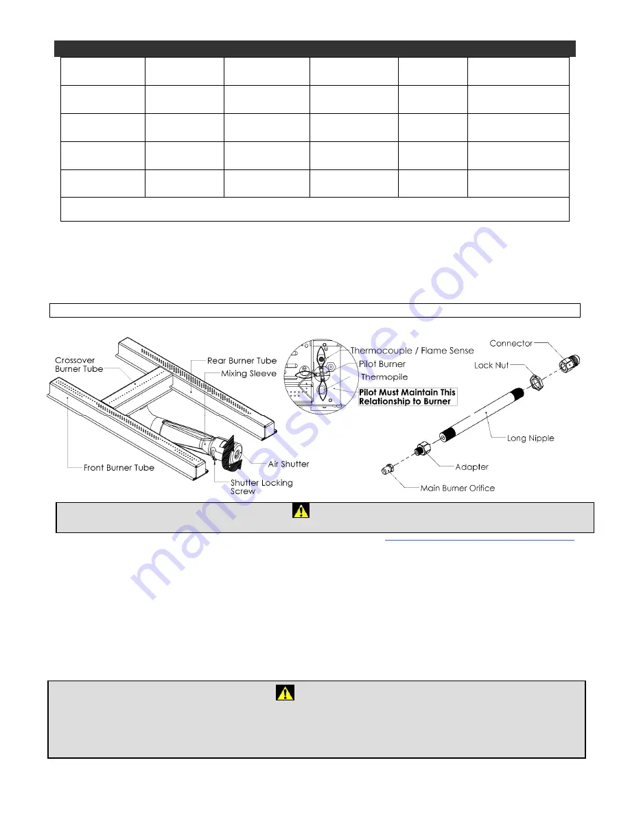
Main Burner Conversion 


1.  Remove the burner tube from the burner system (refer to page 24). 
2.  To adjust the Primary Air Setting, loosen the Air Shutter Adjustment Screw and rotate the Air Shutter to the appropriate 

gap position of the new fuel. A drill bit of the proper diameter or a measuring device such as a caliper maybe used to 
establish the gap opening. 

3.  Replace the old orifice with one for the new fuel. Pipe sealing compound is required to ensure a proper seal between the 

orifice and the adapter fitting. 

4.  For information with regards to the size of the Primary Air Setting and orifice, please refer to page 32. To reinstall the 

burner tube assembly please refer to page 24 & 24. 

Valve Conversion 

The HI/LO diaphragm of the gas valve must be replaced to accommodate the alternate fuel source. Please follow the 
instructions that accompany the conversion kit for the gas valve. 
 

Figure 19 - Main burner fuel conversion guide.

Caution

The gas supply shall be shut off prior to disconnecting the electrical power, before proceeding with the conversion.


WARNING


This conversion kit shall be installed by a qualified service agency in accordance with the manufacturer's instructions and all 
applicable codes and requirements of the authority having jurisdiction. If the information in these instructions is not followed 
exactly a fire, explosion or production of carbon monoxide may result causing property damage, personal injury or loss of life. 
The qualified service agency is responsible for the proper installation of this kit. The installation is not proper and complete until 
the operation of the converted appliance is checked as specified in the manufacturer's instructions supplied with kit.

35

Summary of Contents for Cove MQZDV3927

Page 1: ... followed exactly a fire or explosion may result causing property damage personal injury or loss of life WARNING Improper installation adjustment alteration service or maintenance can cause property damage personal injury or loss of life Refer to this manual Installation and service must be performed by a qualified installer service agency or the gas supplier Do not store or use gasoline or other ...

Page 2: ...tside of Fireplace 20 MQLOGF39 Log Installation 21 22 MQLOGF46 Log Installation 23 24 Burner Installation Removal Guide 25 26 Light Wiring Connections 27 MQRSP39 Glass Rock Tray Conversion Guide 28 MQRSP39 Glass Rock Tray Rock Placement 29 30 MQRSP39 Glass Rock Tray Glass Ember Placement 31 Gas Line Access and Locations 32 Gas Line Installation 33 Millivolt System Lighting and Burner Control 34 Ga...

Page 3: ...Wall Thimble and Roof Support 50 Parts List MQZDV3927 MQZDV4634 51 52 Troubleshooting the Gas Control System 53 Limited Lifetime Warranty 54 3 ...

Page 4: ...used with the installations e g marble tile and the adhesives used to adhere this product to the walls can react with heat and cause odours It is recommended that you burn your gas fireplace or stove for a minimum of four hours at a time with the fan off after the curing of the paint has been completed These odours can last upward to 40 hours of burn time keep burning at a minimum of four hours pe...

Page 5: ...e with 8ga copper wire using a serrated or star washer to penetrate paint or protective coating to insure grounding Use carriage bolt at the attachment point see diagram above to secure the appliance to the floor For required venting components see venting installation in appropriate section of this manual Certified for installation in a bedroom or bedsitting room In Canada this appliance must be ...

Page 6: ...ppliance 15 Installation and repair should be done by a qualified service person The appliance should be inspected before use and at least annually by a professional service person More frequent cleaning may be required due to excessive lint from carpeting bedding material et cetera It is imperative that control compartments burners and circulating air passageways of the appliance be kept clean Ma...

Page 7: ...20 2005 Edition B A carbon monoxide detector shall be located in the room that houses the appliance or equipment and shall Be powered by the same electrical circuit as the appliance or equipment such that only one service switch services both the appliance and the carbon monoxide detector Have battery back up power Meet ANSI UL 2034 Standards and comply with NFPA 720 2005 Edition and Have been app...

Page 8: ... temperature of the vent and help the appliance to vent properly in cold weather conditions It is also important in vertical vented direct vent appliances that the appliance be operated daily during the winter months as this will help stop the termination from freezing up We recommend using a thermostat Thermostats are not permitted for vented Decorative gas fireplaces installed in the U S A set a...

Page 9: ...Fireplace General Dimensions MQZDV3927 MQZDV4634 Figure 3 General dimensions for the fireplace 9 ...

Page 10: ...distance between the front face of the fireplace and the nailing tab is approximately 1 2 1 27cm This implies that 1 2 facing material is required to ensure that the unit is flush with the wall MQZDV3927 MQZDV4634 Figure 4 Side view of framing guide Cold Climate Recommendation When installing this fireplace against a non insulated exterior wall or chase it is recommended that the outer walls be in...

Page 11: ...nfigurations This unit allows for flooring or hearth material to extend 1 3 4 4 4cm above the bottom of the fireplace Refer to the facing material section for dimensions and details Make note of the non combustible material areas The minimum ceiling height for this unit is 5ft 1 52m for the MQZDV3927 and 6ft 1 83m for the MQZDV4634 Please note that it is possible to raise the appliance above the f...

Page 12: ...ace Fireplace and Combustible Wall to be covered with Non Combustible Materials e g Stone around Fireplace Framing Flush with Face of Fireplace Fireplace to be covered with Non Combustibles e g Concrete Board for Flat Wall appearance Qty 2 Nailing Tabs are located on each side of the fireplace front frame 12 ...

Page 13: ... 3 1 2 8 9cm All Vent Systems Side Bottom of Horizontal Pipe 1 2 5cm All Vent Systems 1 2 5cm All Vent Systems 1 2 5cm All Vent Systems 1 2 5cm All Vent Systems Vertical Vent Pipe 1 1 4 3 2cm Simpson AmeriVent Selkirk Direct Temp Systems 1 1 4 3 2cm Simpson AmeriVent Selkirk Direct Temp Systems Figure 1 Facing material installation requirements Table 1 Clearances to combustibles If appliance is in...

Page 14: ...easily combust Check your local codes and regulations to determine whether your mantel is combustible or non combustible The advantage of a non combustible mantel is that they may be extended right up to the tile lip Combustible mantels on the other hand must adhere to the dimensional restrictions shown in Figure 7 MQZDV3927 MQZDV4634 Figure 7 Mantel clearance to combustible materials requirements...

Page 15: ... the glass surface Also initial paint curing can deposit a slight film on the glass It is therefore recommended that initially the glass be cleaned two or three times with non abrasive common household glass cleansers and warm water After that the glass should be cleaned two or three times a season depending on the usage Glass Replacement The MQZDV3927 uses ceramic glass while the MQZDV4634 model ...

Page 16: ... these liner panels as they are fragile Use the supplied brick clips to secure the Side Brick Panels in place 4 Reinstall the baffle using its original screws NOTE When reinstalling the baffle ensure that the integrity of the firebox is not compromised The firebox must remain airtight Use high temperature Millpac to reseal if necessary 5 Reinstall the grate bar assembly 6 To remove simply reverse ...

Page 17: ... wall Replace brick clips and screws 4 Reinstall the baffle using its original screws NOTE When reinstalling the baffle ensure that the integrity of the firebox is not compromised The firebox must remain airtight Use high temperature Millpac to reseal if necessary 5 Replace the left and right filler pieces and the lamp plate on the burner pan Reinstall the grate bar assembly 6 To remove Liners sim...

Page 18: ...de is provided to assist in positioning the upper tab 2 Swing the lower portion of the panel in so that the holes line up with the lower locating dimples Carefully set the panel onto the dimples Cavity Access Cover Plate The Cavity Access Cover Plates provide access to the electrical box and fan assembly optional They are located behind the side liner panels and are sealed with Millpac and fastene...

Page 19: ...ox 5 The variable speed switch may be mounted to the left side of the Front Ledge Channel or wall mounted 6 Seal or re seal the Cavity Access Plate with generous amount of Millpac Refer to illustration for more detail Fan wiring diagram WARNING Electrical Grounding Instructions This appliance is equipped with a three prong grounding plug for your protection against shock hazard and should be plugg...

Page 20: ... pronged grounding plug for your protection against shock hazard and should be plugged directly into a properly grounded three prong receptacle Label all wires prior to disconnection when servicing controls Wiring errors can cause improper and dangerous operation Verify proper operation and servicing Caution Electrical installation to be done by a qualified installer All wires must be connected an...

Page 21: ...Tab 2 and Tab 4 are pulled up Tab 3 must be flat Step 2 Place Log 1 Log 2 onto the ember plates and up against rear brick panel Log 1 will be pulled forward to Tab 1 Log 2 will be pushed up to Tab 2 Step 3 Place Log 3 onto rear light holder and up against Log 2 and left brick panel Log 4 will be placed onto left ember plate as shown and up to Log 2 Do not cover front burner tube Log 8 Log 9 Tab 4 ...

Page 22: ...Log 7 onto the grate bars as shown above Step 6 Add lava rock to the bottom of the burner pan Add glowing embers to the top of the ember plates and front burner tube And sprinkle vermiculite over the lava rock Do not place any media within Pilot Shield Area see above Log 5 Tab 4 Log 1 Log 6 Log 7 Keep Pilot Shield Area Clear 22 ...

Page 23: ... 9 in front of the lights Place Log 1 in between Logs 8 9 Ensure that Tab 3 is pulled up Tab 3 will be used in Step 4 Tab 1 Tab 2 and Tab 4 must be flat Step 2 Place Log 2 on the firebox bottom and up against the right side panel Push back until it contacts the gas pipe Place Log 3 on the firebox bottom Pull forward until it contacts the grate bar stop Log 8 Log 9 Log 1 Tab 2 Tab 3 Tab 4 Tab 1 Log...

Page 24: ...ot in Log 2 as above Step 5 Place Log 6 and Log 7 on the grate bar as shown above Step 6 Add lava rock to the bottom of the burner pan Add glowing embers to the top of the ember plates and front burner tube Sprinkle vermiculite over the lava rock Do not place any media within Pilot Shield Area see above Log 4 Log 2 Log 2 Knot Log 5 Groove Log 3 Tab 3 Log 7 Log 6 Keep Pilot Shield Area Clear 24 ...

Page 25: ...mended 5 Installation is the reverse of these steps Please tighten the burner pan screws in the sequence shown in Figure 15 Burner Tube Removal 1 Remove the logs grate bar assembly and lamp tray 2 Unfasten the ember trays and remove from the unit The burner tube is now loose Please refer to Figure 16 for illustration 3 Slide the burner tube to the left and remove it from the burner pan assembly 4 ...

Page 26: ...er pan with black Millpac Valve Removal Guide 1 Remove the right access panel see page 17 2 Remove the mounting screw attaching the upper valve bracket and lift the valve assembly to disengage the mounting hook 3 Gently remove the valve assembly outside of the fireplace cavity Ensure that the electrical and plumbing connections are not damaged Remove all electrical and plumbing connections to the ...

Page 27: ...to be done at the time of installation Lamp Plate The Lamp Plate is a low voltage halogen system that works in tandem with a solid state step down transformer located in the electrical compartment This is shown in To remove the plate 1 Unfasten the two 2 screws holding the Lamp Plate to the Burner Tray Extensions 2 Unbolt the Securing Nut and remove the Lamp Plate 3 Reverse these steps to reinstal...

Page 28: ... the Burner Tray Extensions These will not be reattached Flip the Lamp Plate around so that the mounting slots are pointing downward Then insert the slots on the Lamp Plate into the mounting slots located in the burner support bracket 3 For Crushed Glass Only Fig 3 Fig 4 Slide Lamp Shield over Lamp Plate Insert tabs of Cover Plate into slots on Lamp Shield See note in Fig 4 4 Align the Glass Rock ...

Page 29: ...lace the MQRSP39 Glass Rock Tray into place as shown in the illustration above All Tabs on ember plates must be flattened before rock placement Step 2 Place Rocks into position as shown Be sure not to place them directly over top of the burner tube Step 3 Place Rocks into position as shown above Rocks must not cover burner ports or fireplace will not operate properly Step 4 Place Rocks into positi...

Page 30: ...e Rocks into position as shown above Rock Setup is complete Lava Rocks may be spread around firebox bottom if desired NOTE If flame impingement on the rocks causes sooting then you may have to move or remove one or more rocks DO NOT PLACE ROCKS DIRECTLY OVER TOP OF THE BURNER TUBE PORTS 3 3 3 3 4 4 6 6 6 30 ...

Page 31: ...er plates will be flat Step 2 Place Decorative Ember Glass into tray area as shown Be sure not to place glass into Pilot Ignition Shield Area Step 3 Glass Embers must not enter this area or fireplace will not operate properly Step 4 Glass Ember installation is complete Lava Rocks may be spread around firebox bottom if desired Discoloration of glass may occur during normal use this does not affect ...

Page 32: ...views above show the following gas line access and locations A Burner to valve B Gas Line to valve routing access C Valve Location Access panels 2 inside firebox must be sealed with 10 screws and a 5 16 bead of black Millpac supplied 32 ...

Page 33: ... from the gas supply piping system during any pressure testing of that system at test pressures in excess of 1 2psig 3 5 KPa 9 The appliance must be isolated from the gas supply piping system by closing its individual shutoff valve during any pressure testing of the gas supply piping system at test pressures equal to or less than 1 2psig 3 5 KPa Note The gas line connection may be made of 1 2 rigi...

Page 34: ...in the red ignitor button until you hear a click Now observe closely the pilot burner located on the rear center left hand side of the main burner If a flame has appeared then continue to depress the control knob for 20 seconds If the flame did not appear then continue to depress the red ignitor button every 5 seconds until a flame is established NOTE If after 30 seconds a flame has not yet been e...

Page 35: ...aks with a soap and water solution DO NOT USE OPEN FLAME FOR LEAK TESTING Main Burner Conversion 1 Remove the burner tube from the burner system refer to page 24 2 To adjust the Primary Air Setting loosen the Air Shutter Adjustment Screw and rotate the Air Shutter to the appropriate gap position of the new fuel A drill bit of the proper diameter or a measuring device such as a caliper maybe used t...

Page 36: ... into the end of the injector Then insert into injector journal and rotate the injector clockwise until a torque of 9 in lbs is achieved 7 Replace the pilot hood by aligning the tab on the base of the hood with the slot in the side of the pilot journal and push the hood down directly onto the pilot bracket Figure 20d The hood must sit squarely on the bracket for proper operation Check to insure th...

Page 37: ...37 ...

Page 38: ...om temperature Note that the pilot assembly may be hot in an intermittent or standing pilot system even if the main burner was never on Exercise caution when working within the area ALL WORK SHOULD BE PERFORMED BY A QUALIFIED AND CERTIFIED TECHNICIAN Monthly Flame Inspection It is recommended to turn on the unit at least once a month and inspect the flame pattern to ensure there are no problems wi...

Page 39: ... advantage to using the battery backup is that in the case of a power failure the appliance is still operable Remote Receiver This component provides the capability of controlling the appliance with a wireless remote transmitter There are two switches to note on the receiver module The first switch on the Remote Receiver module is a 3 position slide switch This switch is used to either manually tu...

Page 40: ...the Remote Receiver module and then proceeds to the Main IPI module Furthermore note that a Backup Battery Pack is not required in this configuration Instead batteries in the Remote Receiver resume the function as a backup supply Electrical Compartment Location The electrical compartment is located on the right side of the appliance outside of the fireplace refer to Figure 21 It is accessible eith...

Page 41: ...N OFF and manual HI LO capabilities OPTIONAL For units with remote HI LO capabilities a modulating servo is required to be installed on the valve The connectors to this servo must be connected to the Remote Harness as shown in the figure above Receiver Module 0 584 523 521 221 1001 P221SI 41 ...

Page 42: ...3 Remote ON OFF variable HI LO and fan capabilities Refer to the Fan Installation Removal Guide section for fan installation 0 584 523 521 221 1001 P221si 0 584 523 521 221 1001 P221SI Receiver Module 1001 P221SI 42 ...

Page 43: ... you don t smell gas go to the next step 8 Turn manual shutoff valve counter clockwise to ON position 9 Close the glass door 10 Turn on all electric power to the fireplace and re install batteries into the Transmitter Receiver and or Battery Backup Pack 11 Turn ON the switch that operates the Main Burner If using a Remote Control refer to Remote Control Operation Manual for activation TO TURN OFF ...

Page 44: ...000 BTUh 3kW 12in 1 30cm minimum for appliances 10 000 BTUh 3kW and 100 000 BTUh 30kW 36in 91cm for appliances 100 000 BTUh 30kW In the USA 6in 2 15cm for appliances 10 000 BTUh 3kW 9in 23cm for appliances 10 000 BTUh 3kW and 50 000 BTUh 15kW 12in 30cm for appliances 50 000 BTUh 15kW K Clearance to a mechanical air supply inlet 6ft 1 8m min 1 in Canada In USA 3ft 91cm above if within 10ft 2 3m hor...

Page 45: ...l venting will help to determine the various vent lengths The maximum horizontal run with the 90 degree bend at the fireplace flue outlet is 4ft 122cm see Figure 25 The maximum horizontal run is 25ft 7 6m when the vertical run is 6 5ft 2 0m see Figure 24 Note 1 4 0 6cm vertical rise is required for every 12 30 5cm of horizontal run The maximum number of 45 degree bends per side wall installation i...

Page 46: ...ial Metric MQZDV3927 MQZDV4634 56 1 2 69 1 2 1 4m 1 8m 4ft 4ft 2 4m 2 4m 6 5ft 2 0m 20ft 6 1m 7ft 2 1m 20ft 6 1m 8ft 2 4m 20ft 6 1m 9ft 2 7m 20ft 6 1m 10ft 3 0m 20ft 6 1m 11ft 3 4m 20ft 6 1m 12ft 3 7m 20ft 6 1m 13ft 4 0m 20ft 6 1m 14ft 4 3m 20ft 6 1m 15ft 4 6m 20ft 6 1m 16ft 4 9m 20ft 6 1m 17ft 5 2m 20ft 6 1m 18ft 5 5m 21ft 6 4m 19ft 5 8m 23ft 7 0m 20ft 6 1m 25ft 7 6m 25ft 7 6m 20ft 6 1m 30ft 9 1m...

Page 47: ...ce the spring spaces provided approximately every two feet to position the inner pipe centered in the outer pipe When forming bends place spring in bend or before and after Horizontal runs require support metal straps every 2ft 0 61m In offset installation support straps should be used to stabilize pipe Expand the coaxial flex pipe system to the point that the outer pipe protrudes approximately 2 ...

Page 48: ... sealant Millpac to the end Then attach the inner pipe to the vent termination with sealant and secure it with the four screws provided At this time make sure the spacer springs are attached to the inner flex pipe Then attach the outer pipe by the same method 4 Mount the vent termination and seal it to wall using caulking around the thimble to weather proof After installing the vent termination do...

Page 49: ...634 Flex is not permitted within roof support 6 When penetrating the roof a rigid galvanized pipe must be used Attach the outer flex pipe to the rigid pipe with high temperature sealant and secure it with four screws The inner flex pipe of the venting system may continue on to attach directly to the termination i e no inner rigid pipe is required It then must be secured the same way with four 4 sc...

Page 50: ...he appearance Clean prime and paint with suitable painting products Wall Thimble and Roof Support The Wall Thimble is used to shield the combustible material from the vent pipe The appropriate size of thimble is required for each model Please contact your local dealer for more information Refer to Figure 26 for wall cutout information The Roof Support is used to secure the vertical venting as it p...

Page 51: ... ZDV5FCL Flex Clamp 5 ZDV7FCL Flex Clamp 7 ZDV5SS Spring Standoff Spacer for Inner Pipe Z57DFA Hard Pipe Adapter 5 8 Part No Description Fireplace Base Unit MQZDV4634N Millivolt MQZDV4634NE IPI DV DECORATIVE FIREPLACE NG 59000Btu 7 10 Flue J Box Lights MQZDV4634LP Millivolt MQZDV4634LPE IPI DV DECORATIVE FIREPLACE LP 55500Btu 7 10 Flue J Box Lights MQZDV4634 Requirements Log Sets Platform Rock or ...

Page 52: ...replaces installed in the U S A Modulating NG GTMRCP Remote Control Millivolt Thermostat Thermostats are not permitted for vented Decorative gas fireplaces installed in the U S A Modulating LP GTFRCN Remote Control Millivolt Thermostat Thermostats are not permitted for vented Decorative gas fireplaces installed in the U S A Modulating Fan NG GTFRCP Remote Control Millivolt Thermostat Thermostats a...

Page 53: ...age Check generator with millivolt meter Take reading at generator terminals of gas valve Should read 325 millivolts minimum while holding valve knob depressed in pilot position and wall switch off Replace faulty generator if reading is below specified minimum Plugged burner orifice Check burner orifice for stoppage and remove Pilot burning no gas to burner valve knob ON and wall switch ON Defecti...

Page 54: ...dential environment c damages caused by any unauthorized alteration or repair of the unit affecting its stability or performance d damages caused by improper matching or application of the unit or the unit s components e damages caused by failing to provide proper maintenance and service to the unit f any expenses incurred for erecting disconnecting or dismantling the unit g parts or supplies used...

Reviews: