NOTE
: Hole location should be 12” from corner and
1/4” above finished floor.
HORIZONTAL INSTALLATION ONLY
This heater may be wired with standard building wiring (rated min-
imum 60° C).
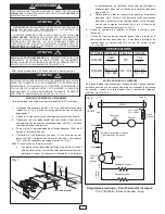
1.
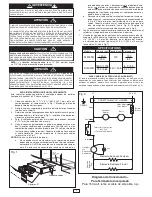
Cut a 14
1
/
4
” x 3
5
/
8
” (361.9 x 92.1 mm) opening at desired
location as shown in Fig. 1. Keep clearance area free of
obstructions.
2.
Remove top cover from heater enclosure by removing the
cover screws.
3.
Determine which knockout in enclosure will be used for field
wiring and remove (see Fig 1). Install strain relief (field
supplied).
4.
Fish field wiring through strain relief leaving 6” (12.7 mm) of
wire inside box.
5.
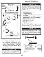
Make wiring connection, attaching field wiring to two (2) black
pigtail leads for 240/208V model, or to black and white pig tail
leads for 120V model with wirenuts (provided). Connect field
ground lead to ground pigtail with wirenut (provided). See
Fig. 2.
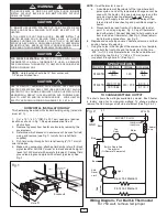
NOTE
: If wall thermostat is used:
a.
A double pole wall thermostat of the type where both
poles cycle on and off by temperature change cannot be
used with this heater. Only one pole may cycle and this
pole must cycle heating element only, not the motor.
Cycling both supply leads will defeat fan delay off fea-
ture and result in over-heating and possible damage to
heater.
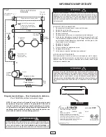
b.
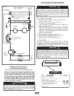
Disconnect blue lead from built-in thermostat lead at
point A on wiring diagram, Fig. 3. Cap off thermostat
lead with wirenut. Connect blue lead to field supply lead
from load side of thermostat. (See Fig. 3) Make remain-
ing field wiring connections per Fig. 3.
6.
Replace and secure top cover on heater enclosure, and then
position heater into opening.
7.
Using the holes in the flanges of the enclosure for a template,
secure both the front grille and the heater by drilling two
.093” (
3
/
32
”)(2.3 mm) diameter holes into the cabinet board
and installing two No. 6 x
3
/
4
” (152.4 x 19 mm) screws
(supplied) through hole “A.” (See Fig. 1).
TO REDUCE RISK OF FIRE OR ELECTRICAL SHOCK,
DO NOT
INSTALL WITHOUT BACK BOX.
DO NOT
OPERATE WITHOUT
GRILLE INSTALLED.
WARNING
2
1.
DO NOT
USE HEATER FOR DRY OUT. PAINT, PLASTER, SAW-
DUST, AND DRYWALL SANDING DUST MUST BE KEPT OUT OF
HEATER.
2. THE HEATER IS HOT WHEN IN USE.
DO NOT
INSTALL THE
HEATER BEHIND DOOR, BEHIND TOWEL RACK, IN CLOSET,
WHERE CURTAINS OR DRAPES COULD TOUCH OR BECOME
SCORCHED BY HEATER, OR WHERE AIRFLOW TO HEATER MAY
BE OBSTRUCTED. KEEP ELECTRICAL CORDS, BEDDING, FURNI-
TURE AND OTHER COMBUSTIBLES AWAY FROM HEATER.
CAUTION
TO CHANGE WATTAGE OUTPUT
The chart shows the wattages available by model. Each heater
is factory wired for its maximum wattage. To change wattage
remove the Red Jumper at left side of element (See Fig. 3 & 4).
Model No Wattage Voltage Amperage
S1500TB
1500
120
12.5
750
6.3
S1504TB
1500 / 1125
240 / 208
6.3 / 5.4
750 / 564
3.1 / 2.7
SPECIFICATIONS
L1
GND
L2 or N
SOCKET PLUG
Black
Blue
Blue
B
lu
e
Thermal
Fuse
Built-in Single Pole
Thermostat
(Or Remote Thermostat)
R
e
d
J
u
m
p
e
r
Rear Coil Element
Front Coil Element
Fan
Delay
Motor
Auto
Reset
Limit
Light
240V-Black
120V-White
!
FOR PROPER OPERATION:
HEATER IS EQUIPPED WITH BUILT-IN
THERMOSTAT. IF A WALL THERMOSTAT IS USED, A SEPARATE
FEED FROM WALL THERMOSTAT TO HEATER IS REQUIRED. SEE
WIRING DIAGRAM FIG 3.
CAUTION
!
USE OF REMOTE THERMOSTAT WHICH SHUTS OFF POWER TO
HEATER DEFEATS FAN DELAY FEATURE AND DOES NOT ALLOW
HEATER TO COOL DOWN AS REQUIRED. WIRING HEATER IN THIS
MANNER WILL RESULT IN OVER-HEATING AND POSSIBLE DAM-
AGE TO HEATER AND/OR SURROUNDINGS. WIRE HEATER
EXACTLY AS SHOWN IN WIRING DIAGRAMS, FIG. 2 & FIG. 3.
CAUTION
!
!
Fig. 2
Wiring Diagram - For Built-in Thermostat
For 750 watt, remove red jumper
14-1/4
3-5/8
CLEARANCE AREA
FOR HEATER
CABINET
Hole "A"
Knock-outs
Fig. 1
Knockouts
Hole “A”

