Original Instruction Manual
Combimatic
Owner’s manual
Page 1: ...Original Instruction Manual Combimatic Owner s manual ...
Page 2: ...re for operation 22 5 2 1 Prepare the grinding wheel 22 2019 Markusson Professional Grinders AB All rights reserved 5 2 2 Set the head tilt angle 23 5 2 3 Set the top plate angle 23 5 2 4 Insert the chain 24 5 2 5 Tighten the chain 25 5 2 6 Set the chain pusher 26 5 2 7 Set the grinding depth 28 5 2 8 Set the cutter top plate to equal lengths 28 5 2 9 Center the grinding disc 28 5 2 10 Set the gri...
Page 3: ... not be used outdoors or in a manner that is not described in this manual 1 4 Regulatory information Regulations are given below A copy of the EC Declaration of conformity is supplied with the machine WARNING Before you install operate or do maintenance on the machine you must read the safety information in this manual Obey the instructions in this manual to prevent injuries or damage to the equip...
Page 4: ... This symbol shows that electrical and electronic equipment must not be disposed of as unsorted municipal waste It must be collected separately Recycle according to current local rules and regulations 762 31 Rimbo Sweden Model Combimatic Mfg 2016 43 Weight 48 kg Auto Chain Grinder Input 12V DC 12A no 3250rpm Arbor Ø 16mm S N 12345 Made in Sweden ...
Page 5: ...e power tool must always be fixed to the floor Make sure that it is safely attached WARNING Do not operate the power tool in explosive atmospheres such as in the presence of flammable liquids gases or dust or near flammable materials Power tools create sparks which may ignite such materials WARNING The user must only do maintenance that is described in this manual on the power tool Only approved a...
Page 6: ...revent that it breaks remove grinding dust every day Use a vacuum cleaner brush or similar to clean the machine 2 3 Signs and symbols See the table below for information about the signs and symbols on the product Sign Symbol Description Warning A warning tells you about conditions that can cause injury or death if you do not obey the instructions Do not continue until all conditions are accepted a...
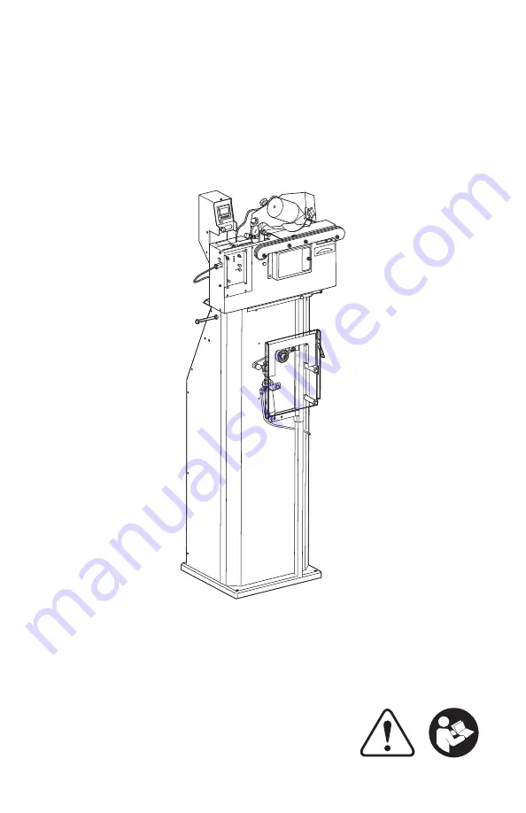
Page 7: ... machine can sharpen chains 3 4 and 404 pitch for power saws forestry machines and harvesters A pneumatic chain tensioner is attached to the stand It secures and tensions the chain when it is sharpened The stand has 2 chain hangers which makes it easier to separate the sharpened chains from chains that are not yet sharpened Accessories are availabe for extra long chains ...
Page 8: ...e machine F Pneumatic chain tensioner Secures the chain in the correct position G Grinding wheel The wheel that sharpens the chain H Grinding wheel centering knob Centers the grinding wheel above the chain I Grinding depth knob Sets the grinding depth for the gullets J Chain pusher adjustment knob Sets the grinding length K Power Supply cable Supplies electricity to the machine L Chain pusher Adva...
Page 9: ...ng grinding C Top plate angle scale Shows the top plate angle on a scale from 0 35 Default 30 It is set using the top plate angle screw O in Front view illustration D Head tilt angle scale Shows the head tilt angle on a scale from 50 90 Default 60 E Wire Controls the vertical movement of the grinding head F Wire adjustment nuts Adjusts the wire that controls the vertical movement of the grinding h...
Page 10: ...e settings of the grinding head and the profiling of the grinding wheel all determine how the chain is sharpened B A C D Pos Part Description A Grinding wheel Grinds the chain B Grinding wheel nut Keeps the grinding wheel in place C Grinding wheel guard Protects the user and grinding wheel when the chain is sharpened D Attachment knobs Secures the grinding wheel guard in place ...
Page 11: ...s Part Description A Chain tensioner rod Where the tensioner slides up and down The tensioner is moved to fit chains of different lengths B Locking handle Locks the tensioner in place C Protection cover Protects the user from pinch injuries D Tensioner roll Allows the chain to move when it is sharpened E Tensioner arm Quick release Allows the user to tension or release the chain faster than if the...
Page 12: ... button Shuts off the power and stops the machine The stop button is used to turn off the machine after operation and to do an emergency shut down E Counter digit buttons Sets the digits in the counter F Grinding wheel motor switch Starts the grinding motor G Troubleshooting indicators Indicates potential problems with the machine See section 7 4 Troubleshooting indicators H Grinding head position...
Page 13: ...low speed the grinding is done in a pulsing motion 3 6 2 Counter The counter consists of a display and buttons that set the number of cutters to be sharpened Before you start the machine use the buttons to program the number of cutting teeth to be sharpened The machine will automatically stop after the programmed number of cutting teeth have been sharpened The lower digits on the display show how ...
Page 14: ...the delivery Outer diameter OD Width W Inner diameter ID 150 mm x 4 8 mm x 16 mm 150 mm x 7 9 mm x 16 mm 150 mm x 9 5 mm x 16 mm Max dimensions for the machine Length L x Width W x Height H 480 mm x 330 mm x 520 mm 18 9 x 12 9 x 20 4 Dimensions stand Length L x Width W x Height H 345 mm x 360 mm x 1070 mm 13 5 x 14 1 x 42 1 Weight of the machine 16 9 kg Weight stand including converter 33 kg Compr...
Page 15: ...n se 1 Unpack the crates Note Keep the delivery crates and packing materials Pack the machine in them if it is moved or sent for service The crates and packing materials will minimize the risk of damage during transportation 2 Make sure that all parts in the list below are included in the delivery Combimatic Auto Chain Grinder machine stand with set of screws nuts and bolts for assembly pneumatic ...
Page 16: ...atic Auto Chain Grinder machine must always be fixed to the floor Make sure that it is safely attached To mount the grinder on the stand begin by assembling the stand The stand comes in 4 pieces two sides one base and one front piece A 2x B 1x C 1x D 2x E 2x I 2x F 3x J 7x G 12x K 3x H 4x L 2x ...
Page 17: ...vided wrench 2 Next attach the two side pieces to each other with provided bolts through the holes at the intersection of two pieces to create the side support piece G J G 3 To complete the assembly of the stand bolt the side support first to the base and then to the front piece 4 5 Assemble the pneumatic chain tensioner To assemble the pneumatic chain tensioner lay the stand on the floor with the...
Page 18: ...ts to fix the bottom part of the rod to the stand After securing both the bottom and the top bring the stand back to an upright position 6 There are two air lines to be attached to the pneumatic chain tensioner one with an air fitting unit attached to the end and one without a fitting 7 Insert the line without the fitting through the hole located on the left side of the stand bringing it from back...
Page 19: ...onnect the AC DC converter unit to the machine plug in the black and red power cable into the control panel through the slot on the left hand side of the machine Note For best performance use the converter provided with the machine WARNING Put the power converter where there is as little dust as possible and out of reach of sparks from the machine 12 To connect the air unit slip the air line that ...
Page 20: ...then the wheel could be damaged DO NOT USE IT CRACKED GRINDING WHEELS MUST BE REPLACED IMMEDIATELY See also section 6 3 Change the grinding wheel and fit the grinding wheel guard Once the grinding wheel has been verified you re ready to begin the install 4 6 Bench mount the machine An alternative to having the grinder on a stand is to bench mount the machine IMPORTANT Althought the machine can be ...
Page 21: ...spin the grinding wheel and check for wheel wobble 8 Conduct a final check for proper assembly by turning on the main power and switching on the wheel power switch while standing to the side Look for vibrations due to wheel oscillation or other interference WARNING Always keep bystanders at a safe distance from a grinder while in operation Note To get the best performance from your grinder ensure ...
Page 22: ...ed make sure that the grinding wheel is not cracked does not vibrate or wobble Perform a ring test see section 4 7 Install and center the grinding wheel If the grinding wheel is damaged it must be replaced immediately see section 6 3 Change the grinding wheel and fit the grinding wheel guard If abnormal vibrations occur during operation immediately stop the machine and check the condition of the g...
Page 23: ...eat steps 4 8 until the grinding wheel profile is the same as the selected profile on the profile template 5 2 2 Set the head tilt angle Note Read the specifications from the chain manufacturer to find out the recommended head tilt angle for your chain 1 Use an adjustable wrench to loosen the head tilt angle nut located on the back of the machine 2 Turn the grinding head to set the desired head ti...
Page 24: ... in both directions 5 2 4 Insert the chain CAUTION Always wear safety gloves protective glasses and any other personal protective equipment suitable for the current work task 1 Check the chain for double cutters 2 left cutters or 2 right cutters or double tie straps and make sure that the chain is not damaged Mark double cutters or double tie straps to make it easier to see them when the chain is ...
Page 25: ... chain 2 Lift the tensioner arm there is a quick release function and place the chain below the tensioner roll 3 Lower the tensioner arm to its bottom position 4 Move the tensioner downward until the chain is tightly secured in its position There should be a gap of about 10 15 mm between the pneumatic piston nut and pneumatic piston where the piston should be visible 10 15 mm ...
Page 26: ...fit shorter chains you can order a longer tensioner You can also order a telescopic chain extension kit if you need to fit longer chains See section 8 Accessories and Spare Parts 5 2 6 Set the chain pusher 1 Press the power button to turn on the machine 2 Press the grinding head positioning button to move the grinding head so that it is tilted in the correct start position for the next cutting lin...
Page 27: ... chain pusher arm now advances the chain forward 6 Visually make sure that the chain pusher stops its movement exactly above the rivet behind the cutting link as illustrated in the image below 7 Set the chain pusher switch to OFF when the grinding head is in its uppermost position and the chain lock is not engaged 8 Repeat steps 5 9 until the chain pusher stops in the correct position CAUTION If t...
Page 28: ...are not equally long turn the equal cutting teeth knob clockwise to increase the length of the right cutter and decrease the length of the left cutter or counter clockwise to decrease the length of the right cutter and increase the length of the left cutter 3 Repeat the sharpening test until the cutter top plates are sharpened to equal lengths See section 3 2 Front view position N and adjust the g...
Page 29: ...2 11 Test the grinding settings 1 Set the chain pusher switch to ON The chain pusher arm will push the chain forward 2 Monitor the grinding wheel movements and check if the chain is sharpened 3 If required Turn the grinding depth knob located on the back of the grinding head to make minor adjustments for the grinding depth 4 If required Turn the chain pusher adjustment to make minor adjustments fo...
Page 30: ...tters that still need to be sharpened on the chain See section 3 6 2 Counter for more information about how to set the Counter 5 3 Operate the machine WARNING Always wear safety gloves protective glasses ear protection and any other personal protective equipment suitable for the current work task WARNING Stop the machine immediately if it does not work correctly Note For a video demonstration of h...
Page 31: ...grinding stops 10 Lift the grinding head to its most upright position 11 Set the grinding wheel switch to OFF 12 Set the chain pusher switch to OFF 13 Lift the tensioner arm quick release function and remove the chain 14 To turn off the power to the machine press the stop button IMPORTANT Grinding dust can interfere with the machine s operation Clean the machine daily to remove all of the grinding...
Page 32: ...grinding wheel 2 Shape the edges of the grinding wheel to make sure that the shape is correct See section 5 2 1 Prepare the grinding wheel 3 Set the top plate angle to 0 See 5 2 3 Set the top plate angle 4 Set the head tilt angle to 60 See 3 6 1 Grinding speed knob 5 Remove the screw holding the chain pusher Remove the chain pusher Attach the shorter change pusher Attach and fasten the screw 6 Cha...
Page 33: ...m the screws that holds the ruler in place 4 mm 4 3 Replace the 4 mm distances with the 2 5 mm distances that can be found in the packing material for the machine 4 Mount the outer ruler with the 4 M6 nuts 2 5 mm 4 5 Turn the nut A in 1 1 5 turns clockwise until the groove in the chain vise is 0 8 mm wide in locked position 6 Next you need to set the chain pusher again See section 5 2 6 Set the ch...
Page 34: ... must only do maintenance that is described in this manual on the machine Only approved and trained service technicians can do service on the machine 6 2 Frequency of maintenance Maintenance Step When Description Cleaning Daily Clean the machine daily to remove grinding dust Use a vacuum cleaner or brush to clean the machine Change grinding wheels When worn or damaged See section 6 3 Change the gr...
Page 35: ...e grinding wheel axis and discard it in accordance with local state and national laws and regulations 6 Place a new grinding wheel A on the grinding wheel axis 7 Tighten the nut B by hand to secure the grinding wheel in its position Do not over tighten the nut 8 Place the grinding wheel guard C in its position and fasten the 2 knobs D 9 Center the grinding wheel following the instructions in 5 2 9...
Page 36: ... make sure that the wire is set correctly If necessary adjust or replace the wire 1 Press the power button to turn on the machine 2 Set the grinding speed knob to high speed See section 3 6 1 Grinding speed knob 3 Press the grinding head positioning button to turn the grinding head to the left 4 Set the top plate angle to 30 See section 5 2 3 Set the top plate angle 5 Set the chain pusher switch t...
Page 37: ...ange for a shorter time turn the 2 nuts D in the direction towards the machine for a longer time turn the 2 nuts D in the direction from the machine 9 Repeat steps 5 8 until the test is successful 6 7 Service WARNING The user must only do maintenance that is described in this manual on the machine Only approved and trained service technicians can do service on the machine Contact the reseller if t...
Page 38: ...w to learn how to use the machine or if the chain is not sharpened as expected Recommendation Use an old chain for the test 1 Insert a test chain into the machine and sharpen it according to the instructions in section 5 Operation 2 Test the functions of the machine and study its motions 3 Make sure that the right outer and left inner cutters are sharpened to even lengths Use a slide gauge to meas...
Page 39: ... in the other when the grinding head turns in the 2 different directions The M6 nuts needs to be adjusted See section 5 2 3 Set the top plate angle Wrong parts of the cutters are sharpened The pitch adjustment wing is not in the correct position for the type of chain used See section 5 2 6 Set the chain pusher A cutter was caught on the chain pusher because the chain pusher is worn out and the mat...
Page 40: ...r discard the chain 1 2 3 4 The grinding motor indicator shows a red light Shows that the grinding motor is broken Contact your regional sales representative to reach your service team 1 2 3 4 The chain pusher motor pulse indicator shows a flashing red light Shows the speed of the pulsing motor of the grinding head This is not an error indication The turning motor pulse indicator is purely informa...
Page 41: ...ain loops 14 600C Chain weight Used to tension chain when machine is not mounted on the stand with air tensioner 760 1 5 kg chain weight 860 2 kg chain weight Exhaust pipe Metal nozzle with hose attached to the grinding head Connect to v acuum cleaner not included 808 Air cooling kit Cools the chain during sharpening to protect the metal in the cutting teeth from loosing their strength An air cool...
Page 42: ...42 Combimatic_v2_EN_ 210315 Combimatic Accessories and Spare Parts 25 27 24 23 26 28 1 2 3 4 5 6 7 9 10 8 12 13 14 18 15 16 17 19 20 21 22 11 ...
Page 43: ...12 029 11 Wiring harness 13 102 12 Chain vise 16 221 13 Chain washer 16 207 14 Control panel assembly 16 209 15 PDE bearing 12 032 16 Control unit PCB 16 211 17 Bolt M6 x 30 12 034 18 Stop arm optional 12 035 19 Wire lifter assembly 13 108 20 Pneumatic valve assembly 13 605 21 Lock axis assembly 12 037 22 Motor housing 16 050 23 Potentiometer 13 109 AI Knob to potentiometer 13 109B 24 Counter 13 1...
Page 44: ...44 Combimatic_v2_EN_ 210315 Combimatic Accessories and Spare Parts 31 30 43 29 44 42 41 40 39 38 37 36 35 34 33 32 ...
Page 45: ...wheel nut 13 118 34 Grinding wheel see section 8 2 List of accessories for ordering information 35 PDE bearing 12 062 36 Turning arm assembly 13 119 37 Axis 13 120 38 Center spring 12 061 39 Degree beam 17 122 40 Wire 12 066 41 Ball bearing 6000 2RS 12 065 42 Grinding motor 16 057D 43 Adjusting nut 13 128 44 Grinding head assembly 17 115M Spare Part Order No Converter 115 V 805B Converter 230 V 80...
Page 46: ...46 Combimatic_v2_EN_ 210315 Combimatic Declaration of conformity 9 Declaration of conformity ...
Page 47: ...Sold and distributed by ...