


9
EN
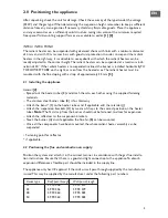
3.7 Shutting down the heater
For short periods of time:
– Set the room thermostat to the minimum temperature.
For longer periods of time:
– Set the room thermostat to the minimum temperature.
– Close the gas tap.
– Switch off the main switch.
3.8 Conversion to another type of gas
The appliance may only be converted to another type of gas by an authorised person. Consult
the manufacturer in order to obtain the correct parts and instructions.
4.0 Maintenance
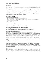
4.1 General
The appliance must be maintained at least once a year, more often if necessary. If applicable, ask a
qualified installer for maintenance advice. When performing maintenance, the appliance must have
been shut down for an extended period. Make sure that you comply with all safety rules.
– Check the position of the ionisation and ignition electrodes
[11]
. If necessary, correct and/or
clean them.
– Check the burner and return pipes for soot and/or condensation. If necessary, clean them.
– Check the connections between the flanges and bend to make sure that they are still com-
pletely tight.
– Open the gas stop cock, switch on the main switch and set the room thermostat to its highest
setting.
– With the appliance in operation, check the burner pressure and the flame quality.
– Check the flame protection by closing the gas stop valve.
4.2 Cleaning
Flue fan:
Before cleaning the flue fan, it is necessary to switch off the main switch and close the gas stop
cock.
After undoing the screws on the flue fan, the fan wheel and the spiral housing can be cleaned
using a brush and/or an air gun.
5.0 Description of parts
Faulty parts may only be replaced by original parts from the manufacturer.
5.1 Air pressure switch [12]
The differential pressure switch checks the transport of the combustion gases. If no or insuffi-
cient combustion-gas transport is detected, the feed to the gas control is interrupted.
Setting: Adjusted at the factory.
D
Adjustment disc
E
Low pressure connection
F
High pressure connection
Summary of Contents for Infra 13
Page 2: ...2 ...
Page 13: ... 0 1 1 2 2 2 2 1 34 5 5 6 7 8 0 9 1 7 8 708 0 1 0 7 8 0 9 9 13 EN ...
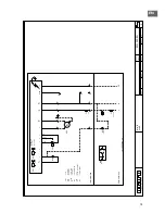
Page 14: ...8 0 Electrical diagram INFRA 50 14 0 0 0 0 0 12 3 3 4 5 6 7 8 0 9 6 7 6 7 0 6 7 8 8 5 0 ...
Page 15: ...EN 15 0 0 1 0 23 4 4 5 6 7 8 0 9 6 7 6 7 0 6 7 8 8 1 ...
Page 16: ...16 ...
Page 27: ... 0 0 1 2 2 3 1 45 2 2 67 8 8 4 5 9 0 1 2 1 1 2 1 1 0 5 9 27 DE ...
Page 29: ...DE 29 0 0 1 2 34 0 0 56 7 7 3 14 8 9 0 9 9 0 9 1 14 8 ...
Page 30: ...30 ...
Page 41: ... 0 0 1 2 3 23 4 5 6 5 6 0 7 4 1 8 9 9 6 0 6 3 4 7 4 4 1 4 4 5 75 75 3 6 41 FR ...
Page 43: ...FR 43 0 1 2 12 3 4 5 5 6 3 0 7 8 8 9 2 3 6 9 93 3 0 3 9 3 5 65 65 2 4 ...
Page 44: ...44 ...
Page 55: ...55 NL 0 1 01 2 2 3 2 45 6 6 7 8 9 1 2 8 9 8 9 2 8 9 1 ...
Page 57: ...NL 57 0 0 1 1 2 3 1 2 45 6 6 7 8 9 0 1 8 9 8 9 1 8 9 0 2 ...
Page 58: ...58 ...
Page 69: ...PL 69 0 0 1 0 0 1 2 32 4 34 5 6 7 7 8 0 9 0 5 5 6 5 5 2 0 0 4 A 2 5 2 B 2 AC C C 4 0 ...
Page 71: ...PL 71 0 0 1 0 0 1 2 32 4 34 5 6 7 7 8 0 5 9 0 5 6 2 0 0 4 A 2 2 B 2 AC C C 4 5 0 ...
Page 72: ...72 ...
Page 83: ...RO 83 0 1 2 3 1 2 3 0 2 1 4 5 1 2 4 6 7 7 8 1 9 0 5 9 90 0 0 9 0 5 1 ...
Page 85: ...RO 85 0 1 2 1 2 1 3 4 1 3 5 6 6 7 8 9 4 8 9 8 9 8 9 4 0 ...
Page 86: ...86 ...
Page 97: ...SK 97 0 1 2 3 45 3 6 76 8 78 9 4 3 A BC D D E F 8 9 G E F E9F 6 0 9 6 H 0 9 E F 690 I I I 8 ...
Page 99: ...SK 99 0 1 2 34 2 5 65 7 67 8 9 9 3 2 AB C C D E 7 8 9 F D E D8E 5 8 9 5 G 8 D E 58 H H H 7 ...
Page 100: ...100 ...
Page 114: ... 1 ...
Page 116: ... 2 ...
Page 117: ... 3 4 TYPE 13 ...
Page 118: ... 4 TYPE 22 ...
Page 119: ... 4 TYPE 38 ...
Page 120: ... 4 TYPE 50 4 TYPE 22 MONO ...
Page 121: ... 4 TYPE 38 MONO 5 Type A 6 Type B12 ...
Page 124: ... 8B 8B Type C32 ...
Page 125: ... 9 ...
Page 126: ... 10 ...
Page 127: ... 11 INFRA INFRA 50 12 ...


