


8
3.0 Start-up / shutdown
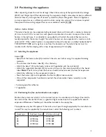
3.1 General
Before being packed, each appliance is fully tested for safety and correct operation. This includes
the setting of the gas pressure and burner pressure. However, always check the burner pressure
and the pre-pressure. Never turn set screws incorrectly. Do not forget to instruct the user on
the proper use and operation of the appliance and peripherals. When a new Infra unit is started
up for the first time it will produce some smoke, as a result of the evaporation of the preserva-
tive oils present. It is therefore necessary to ensure sufficient ventilation during start-up. A newly
installed Infra should be allowed to operate for at least 1 hour before starting a flue gas analysis.
This prevents the measuring equipment being damaged.
3.2 Checking activities:
– Switch off electricity main switch.
– Set the room thermostat to the minimum temperature.
– Open the gas stop cock, then carefully purge the gas pipes and check for leaks. Under no
circumstances use an open flame!
– Close gas stop cock.
– Switch on electricity main switch.
– Set room thermostat to maximum temperature.
– Open the gas stop cock, the appliance will now start up.
3.3 Check that the room thermostat functions correctly
At a setting below the ambient temperature the burner should switch
off. At a setting higher than the ambient temperature the burner should ignite.
3.4 Check the burner pressure: [10].
Connect a gas pressure gauge to the pressure-measuring nipple and measure the burner
pressure (A). The burner pressure can be corrected by adjusting the screw (C) of the pressure
regulator (anti-clockwise gives a lower pressure; clockwise a higher pressure). For high/low the
following applies: to set the burner pressure for maximum load, you can turn the outermost set
nut (SW10) (H) until the correct pressure is achieved. To set the burner pressure to the low
position, you can turn the innermost set net (G) until the correct pressure is achieved. See table
[1]
for the correct burner pressure. PLEASE NOTE: After the measurement the pressure-mea-
suring nipple should be closed again.
3.5 Check the pre-pressure
Make sure that the appliance cannot be switched off by the room thermostat during checking.
Do this by setting the thermostat to its maximum temperature. Then connect a gas pressure
gauge to the pressure-measuring nipple and measure the gas pre-pressure. See table
[1]
for the
correct gas pre-pressure.
3.6
Finally, check that the operation of the appliance cannot be influenced by other objects close to
the unit. In particular, pay attention to items with potential for explosive or corrosive fumes, etc.
Summary of Contents for Infra 13
Page 2: ...2 ...
Page 13: ... 0 1 1 2 2 2 2 1 34 5 5 6 7 8 0 9 1 7 8 708 0 1 0 7 8 0 9 9 13 EN ...
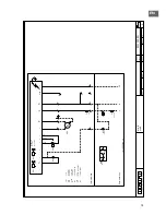
Page 14: ...8 0 Electrical diagram INFRA 50 14 0 0 0 0 0 12 3 3 4 5 6 7 8 0 9 6 7 6 7 0 6 7 8 8 5 0 ...
Page 15: ...EN 15 0 0 1 0 23 4 4 5 6 7 8 0 9 6 7 6 7 0 6 7 8 8 1 ...
Page 16: ...16 ...
Page 27: ... 0 0 1 2 2 3 1 45 2 2 67 8 8 4 5 9 0 1 2 1 1 2 1 1 0 5 9 27 DE ...
Page 29: ...DE 29 0 0 1 2 34 0 0 56 7 7 3 14 8 9 0 9 9 0 9 1 14 8 ...
Page 30: ...30 ...
Page 41: ... 0 0 1 2 3 23 4 5 6 5 6 0 7 4 1 8 9 9 6 0 6 3 4 7 4 4 1 4 4 5 75 75 3 6 41 FR ...
Page 43: ...FR 43 0 1 2 12 3 4 5 5 6 3 0 7 8 8 9 2 3 6 9 93 3 0 3 9 3 5 65 65 2 4 ...
Page 44: ...44 ...
Page 55: ...55 NL 0 1 01 2 2 3 2 45 6 6 7 8 9 1 2 8 9 8 9 2 8 9 1 ...
Page 57: ...NL 57 0 0 1 1 2 3 1 2 45 6 6 7 8 9 0 1 8 9 8 9 1 8 9 0 2 ...
Page 58: ...58 ...
Page 69: ...PL 69 0 0 1 0 0 1 2 32 4 34 5 6 7 7 8 0 9 0 5 5 6 5 5 2 0 0 4 A 2 5 2 B 2 AC C C 4 0 ...
Page 71: ...PL 71 0 0 1 0 0 1 2 32 4 34 5 6 7 7 8 0 5 9 0 5 6 2 0 0 4 A 2 2 B 2 AC C C 4 5 0 ...
Page 72: ...72 ...
Page 83: ...RO 83 0 1 2 3 1 2 3 0 2 1 4 5 1 2 4 6 7 7 8 1 9 0 5 9 90 0 0 9 0 5 1 ...
Page 85: ...RO 85 0 1 2 1 2 1 3 4 1 3 5 6 6 7 8 9 4 8 9 8 9 8 9 4 0 ...
Page 86: ...86 ...
Page 97: ...SK 97 0 1 2 3 45 3 6 76 8 78 9 4 3 A BC D D E F 8 9 G E F E9F 6 0 9 6 H 0 9 E F 690 I I I 8 ...
Page 99: ...SK 99 0 1 2 34 2 5 65 7 67 8 9 9 3 2 AB C C D E 7 8 9 F D E D8E 5 8 9 5 G 8 D E 58 H H H 7 ...
Page 100: ...100 ...
Page 114: ... 1 ...
Page 116: ... 2 ...
Page 117: ... 3 4 TYPE 13 ...
Page 118: ... 4 TYPE 22 ...
Page 119: ... 4 TYPE 38 ...
Page 120: ... 4 TYPE 50 4 TYPE 22 MONO ...
Page 121: ... 4 TYPE 38 MONO 5 Type A 6 Type B12 ...
Page 124: ... 8B 8B Type C32 ...
Page 125: ... 9 ...
Page 126: ... 10 ...
Page 127: ... 11 INFRA INFRA 50 12 ...


