background image

14

COMMISSIONING  

Check that all cable sizes, circuit breakers and wire connections are correct before following below com-

missioning steps:

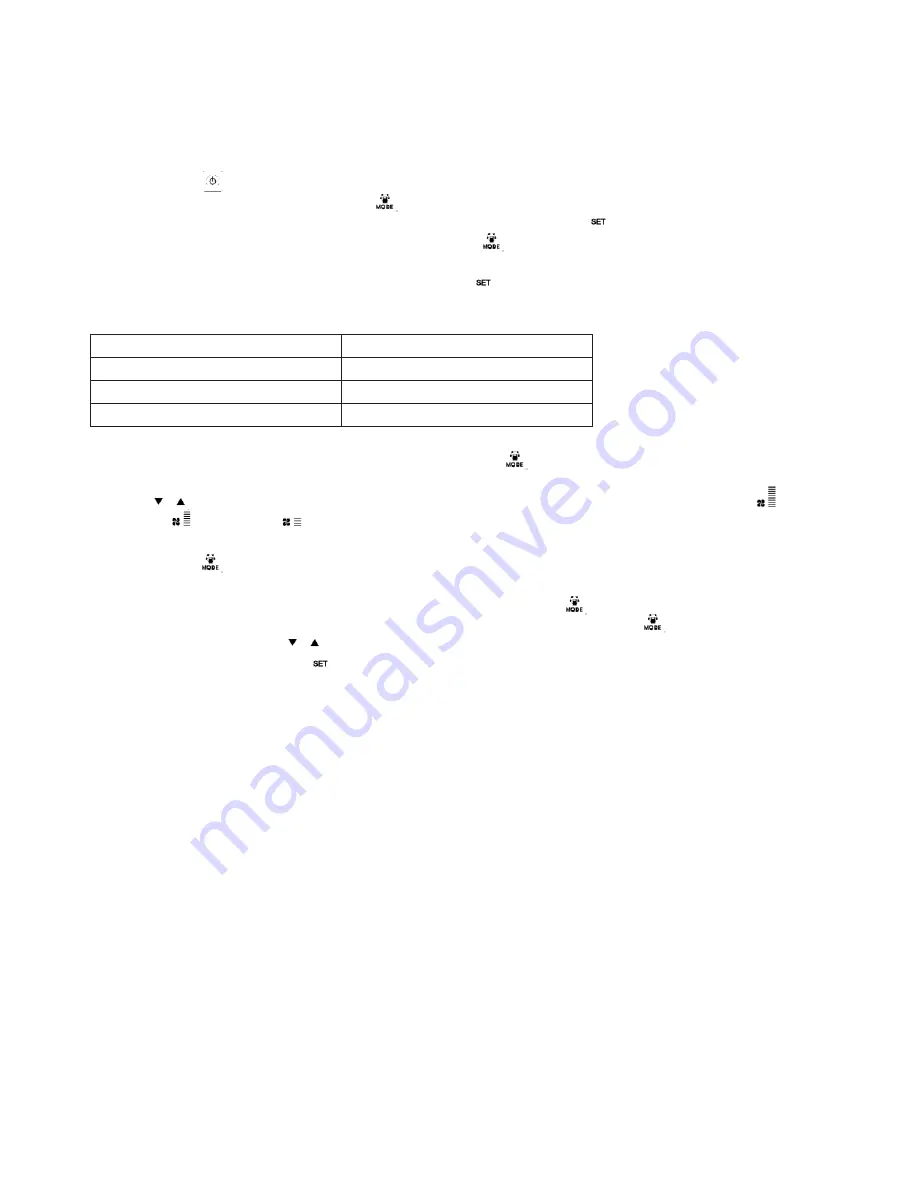
1�  Press button      to turn on/off the ventilator�

2�  Match the correct speed to ERV� Press     for 6 seconds to enter parameters setting and at this time the 

parameter number is shown in the middle of the screen, press button     to switch to parameter No� 21 

(refer to parameters list in comming page) then press      shortly to enter the parameter setting, default 
value “0” flesh at the top right corner, press UP and DWON buttons to change the value according to 

below table (ERV code Vs Models) then press button      again to confirm setting. With the same way to 

change parameters number 23 to be value 2 (10 speeds DC fan control).

Code

Models

3

ERV500

2

ERV1000

2

ERV2000

3�  Then check the mode and fan speed switch� Press button      shortly to switch to OA, RA, SA or EA    

mode, check whether the temperature of the corresponding mode is correct� Under SA or RA mode, 

Press          to switch the fan speed, check if the airflow is adjusted corresponding to H speed      , 

  M speed      and L speed     � 
4.  Check the operation of bypass. The default opening temperature of bypass is 19-21C (adjustable), 

press button      to check the temperature of OA� If the present OA temperature is among 19-21C, 
then bypass will open automatically� If the OA temperature is not within 19-21C, say 18C, then press      
button more than 6 seconds to enter the parameter setting� Press      button to switch to parameter 

number 02, default value 19 flashes shown at the top right corner, Then press       button shortly to en-
ter setting, by pressing          buttons and set the value to be “X”, “X” should be less than 18C (present 
OA temperature), then press      again to confirm. with the same way to set parameter number 03 
value to be “Y”, if “X”<OA temperature>“X+Y”� then bypass will open automatically, after bypass open, 
user can adjust the values under parameters 2 and 3 to make OA<“X” or OA>“X+Y”, then bypass will 
close automatically, please pay attention that bypass open/closed will be around 1 minute delayed� 

Summary of Contents for ERV1000

Page 1: ...Technical Manual EN ERV HEAT RECOVERY UNIT 0661030 ...

Page 2: ... Unit Specifications 5 Dimensioned Drawings 6 7 Installation Considerations 8 9 10 Electrical Installation 11 Wiring Diagrams 12 13 Commissioning Information 14 Intelligent Controller 16 to 24 Modbus Table 25 Dial switch 26 Maintenance 27 ...

Page 3: ...arth leakage protection should also be installed to avoid risk of electric shock or fire The cover of wiring box must be pressed down and closed to avoid dust and dirt ente ring Excess dust and dirt can cause over hea ting of terminals and result in fire or electric shock Installation engineers must follow this man ual strictly Improper action can create a health hazard and reduce efficiency of th...

Page 4: ...es are present Acidic or alkali environments can cause poisoning or a fire Do not use the units as the primary kit chen extract grease and fatty deposits can block the heat exchanger filter and pose a fire risk Do not install the unit near open flame as it may result in over heating and pose a fire risk Rated supply voltage must be maintained otherwise this may cause fire SAFETY CONSIDERATIONS ...

Page 5: ...eds Supply 10 Speed Fan Control Fan Speeds Exhaust 10 Speed Fan Control Summer Bypass Yes Automatic with adjustable range Defrost Yes Automatic with adjustable range CO2 Control Optional controller available On Off control with adjustable range Humidity Control Optional controller available On Off control with adjustable range Fan Boost Contacts Yes 1x available connection to Contact Closed Boost ...

Page 6: ...6 DIMENSIONED DRAWINGS ERV1000 MODEL ERV500 MODEL ...

Page 7: ...nts for each unit The table below shows the dimen sions of the image above and the two images previously the letter in the table represents the letter on the diagram Model L L1 W W1 W2 H H1 C G N ERV500 962 890 904 960 500 270 111 107 19 ø 194 ERV1000 1322 1250 1134 1190 678 388 170 85 19 ø 242 ERV2000 1322 1250 1134 1190 678 785 170 150 19 280 650 ...

Page 8: ... allow access for filter maintenance 1 Be sure the ceiling height is no less than the Figures in above table B column 2 Unit must not be installed close to boiler flues 3 Following phenomenon should be avoided in the ducting installation Dimensions Celling Height Model A B ERV500 904 320 ERV1000 1134 440 ERV2000 1134 835 Serve bends Multiple direction changes Multiple reducers crimped duct ERV500 ...

Page 9: ... or frost when saturation curve is formed from A to C Use pre heater to ensure conditions are kept to right of the curve B to B to move C to C to prevent condensation or frost formation 8 To avoid the outdoor exhaust air cycling back to indoor the distance between the two vents installed on the outside wall should be over 1000mm 9 If heater is equipped to the unit operation of heater should be syn...

Page 10: ...Uneven installation will also effect damper operation Notes for reverse installation of the unit 4 Reverse labeling shows the unit is upside down Ducting 1 Connection of unit vents and ducts should be taped or sealed to prevent air leakage and should com ply to relevant guidelines and regulations 2 The two outdoor vents should face downward toward the outside to prevent any rain water ingress angl...

Page 11: ...Power supply is AC220V 50HZ 1 Phase Open the cover of electrical box connect the 2 wires L N to the terminals and connect the cable of the control panel to the board according to the wiring diagram and join the control panel to the cable We do not accept any liability for any problems caused by the user s self and non authorized re engineering to the electrical and control systems Model Spec of po...

Page 12: ...12 WIRING DIAGRAMS ERV500 AND ERV1000 MODEL ...

Page 13: ...13 EN ERV2000 MODEL ...

Page 14: ...ure of the corresponding mode is correct Under SA or RA mode Press to switch the fan speed check if the airflow is adjusted corresponding to H speed M speed and L speed 4 Check the operation of bypass The default opening temperature of bypass is 19 21C adjustable press button to check the temperature of OA If the present OA temperature is among 19 21C then bypass will open automatically If the OA ...

Page 15: ...usly in an abnor mal status may cause failure electric shock or fire Clean the filter regularly A blocked filter may result in poor indoor air quality Don t put fingers or objects into vents of fresh air or exhaust air supply Injury may be caused by the rotation of the impeller Don t put any burner directly facing the fresh air discharge otherwise it may cause an insufficient burning Don t change ...

Page 16: ...NTROLLER Control Panel The intelligent controller is surface mounted and comes with a touch screen LCD display screen The stan dard connection cable is 5 meters but you can prepare extra cable if necessary Display screen and Buttons ...

Page 17: ... ON status backlit LCD display lights up in OFF status backlit LCD display off without operation for 6 seconds backlit LCD display off too By pressing ON OFF button for around 6 seconds can lock and unlock the controller 2 Mode switch press MODE button to choose display the RA OA FR EA SA Setting CO2 status or Humidity control status ...

Page 18: ...sor is connected ERV runs at boost speed when CO2 con centration higher than setting value 3 The humidity symbol appears when the temperature and humidity sensor is connected ERV runs at boost speed when humidity higher than setting value Under humidity control mode users can set the setting humidity by pressing up and down button The setting range is 45 90 And the Dial switch SW4 3 on the PCB sho...

Page 19: ...e detailed setting introduction 6 Filter alarm When running time of ventilator is over the setting filter alarm time the filter alarm symbol flashes to remind user clean replace the air filters After filters being cleaned replaced please sweep the filter alarm by setting parameter Number 24 value 1 Code Error E1 Fresh air temperature sensor error E2 EEPROM error E3 Return air temperature sensor er...

Page 20: ... Please refer to below valid parameters table to set the suitable parameters according to different requests No Contents Range Default Unit Record Position 00 Power to auto restart 0 1 1 Main control 01 Electrical heater available 0 1 0 Main control 02 Bypass opening temperature X 5 30 19 C Main control 03 Bypass opening temperature rangeY 2 15 3 C Main control 04 Defrosting interval 15 99 30 Minu...

Page 21: ...n will run at high speed automatically for defrosting and supply fan will stop until EA side temperature higher than defrosting entering temperature 15 C for 1 minute or the defrosting time is longer than 10 minutes parameter 06 5 Parameter 07 refers to CO2 concentration control function optional After connecting the optional CO2 sensor the CO2 symbol will display on the screen If CO2 concentrati ...

Page 22: ...e setting day setting weekly timer on and weekly timer off setting A Time setting under time setting interface press SET button for short at this time hour flashes press UP and DOWN button to change hour After setting hour press MODE button for short to switch to minute setting at this time minute flashes press Up and Down button to change minute After time setting press SET button to save and ret...

Page 23: ... press SET button time after time to select Monday period 1 to Sunday period 2 namely Monday period 1 to Sunday period 2 After selecting the day press ON OFF button to confirm timer on is valid invalid When timer on is valid press MODE button to enter hour setting by pressing UP and DOWN button to set hour After hour setting press MODE button to enter minute setting After minute setting press SET ...

Page 24: ...N OFF button to confirm the timer off is valid invalid When timer off is valid press MODE button to enter hour setting by pressing Up and Down button to set hour after hour setting press MODE button to enter minute setting after minute setting press SET button to save and switch to the next day timer off setting and repeat the above steps to set all days and periods timer off After setting all the...

Page 25: ...eed 10 Main control 11 Exhaust fan speed Fan speed 0 stop 2 speed 1 3 speed 2 5 speed 3 8 speed 4 9 speed 5 10 speed 6 11 speed 7 12 speed 8 13 speed 9 14 speed 10 Main control 12 Room temperature observed value Main control 13 Outdoor temperature observed value Main control 14 Exhaust air temperature observed value Main control 15 Defrosting temperature observed value Main control 16 External ON ...

Page 26: ... minutes 3 If the exhaust air temperature 1 C and the outdoor air temperature 15 C the OA heater switches on for 10 minutes for defrosting 4 If the OA heater is on and temperature of outdoor air is 25 C then OA heater will stop for 5 minutes If the outdoor air temperature is detected over 25 C by sensor over 3 times electrical heater stops 2 SW4 2 is the by pass mode Default is off it means that b...

Page 27: ... the side of the unit 3 Vacuum the filters to get rid of the dust and dirt For bad conditions dip it into water with soft wash to clean 4 Push the filters to the positions after they get dried naturally close the access door 5 Change the filters if they are badly affected with dust and dirt or if they are broken Maintenance of heat exchanger 1 Pull off the filters first 2 Draw out the exchanger fr...

Page 28: ...m be www markbelgium be MARK DEUTSCHLAND GmbH MAX PLANCK STRASSE 16 46446 EMMERICH AM RHEIN DEUTSCHLAND TELEFON 49 0 2822 97728 0 TELEFAX 49 0 2822 97728 10 info mark de www mark de MARK POLSKA Sp z o o UL KAWIA 4 16 42 200 CZE STOCHOWA POLSKA PHONE 48 34 3683443 FAX 48 34 3683553 info markpolska pl www markpolska pl S C MARK ROMANIA S R L STR KOS KAROLY NR 1 A 540297 TARGU MURES ROMANIA TEL FAX 4...

Reviews: