Mark Levinson ?585 Quick Start Manual Download Page 9

7

N

0

585 INTEGRATED AMPLIFIER


/


QUICK-START GUIDE

NOTE: 

For complete information about the rear-

panel connections, see the 

N

0

585 User Guide. at www.

marklevinson.com.

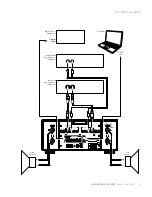
Left and right channel loudspeaker binding posts: The 
Nº585 utilizes custom-made, gold-plated, high-current 
loudspeaker binding posts. The positive binding posts, 
l (positive), are red; the negative binding posts are 
black and are labeled – (negative).

The binding posts can accommodate speaker cables 
terminated in untinned bare wire, spade lugs and banana 
plugs. 

CAUTION: DO NOT OVERTIGHTEN the binding posts. The 
innovative design of these binding posts provides more 
leverage; hence, high-contact, tight pressure connections 
are achieved when finger-tightened. DO NOT FORCE the 
binding post “wings” over a bent or oversized connector. 
Doing so may damage the binding post.

NOTE:

 The audio outputs of this power amplifier are 

considered Class 2 (CL2) circuits in North America. 
This means the wire connected between this amplifier 
and the speaker(s) shall be rated at minimum Class 
2 (CL2) and shall be installed according to the U.S. 
National Electrical Code (NEC) Article 725 or Canadian 
Electrical Code (CEC) Section 16.

Line output connectors: These RCA connectors provide a 
line-level left-channel and right-channel signal that can be 
used to send the selected input to a powered subwoofer, to 
a second listening zone or to recording components such 
as CD recorders or tape decks.

The Line outputs are configured in the Setup menu as 

Fixed 

(for use with recording components or a second audio 
zone). When configured as 

Fixed, the Line outputs are not 

affected by any of the N

0

585's front-panel controls except 

for the Polarity button. 

If your system  includes a powered subwoofer you can 
configure the Line Outputs in the Setup menu as 

Variable.  

When so configured, the Line Outputs will follow the 
settings of the Volume, Balance and Mute controls.

Balanced analog input connectors: These connectors 
accept left-channel and right-channel balanced input 
signals from source components with balanced (male XLR) 
output connectors.

Balanced connector pin assignments:

•  Pin 1: Signal ground

•  Pin 2: (non-inverting)

•  Pin 3: Signal – (inverting)

•  Connector ground lug: Chassis ground


Balanced

Input Connector

(female XLR)

Pin

3

Pin

3

Pin

1

Pin

1

Pin

2

Pin

2

Balanced

Output Connector

(male XLR)

Single-ended input connectors: These connectors accept 
left-channel and right-channel single-ended input 
signals from source components without balanced output 
connectors. 

Digital input connectors: The N

0

585 has six digital  audio 

input connectors: An AES/EBU-format XLR connection 
(numbered 1), two coaxial (RCA) S/PDIF connections 
(numbered 2 and 3), two optical (TOSLINK)  S/PDIF 
connections (numbered 4 and 5) and a USB-B digital audio 
connection (numbered 6).

USB port: This USB Type-A connector allows you to 
perform firmware upgrades that may be offered in the 
future. Check our Web site (www.marklevinson.com) for 
available updates; if one is offered, follow the instructions 
on the Web site. The USB port also allows  you to import 
and export setup configuration information via a USB 
memory stick, and provides a means to update the N

0

585's 

firmware. See the 

N

0

585 User Guide for more information.
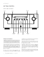
GETTING STARTED

Summary of Contents for ?585

Page 1: ...INTEGRATED AMPLIFIER QUICK START GUIDE N0 585...

Page 2: ......

Page 3: ...ons Troubleshooting 14 Specifications 15 This quick start guide contains all the information you will need to unpack your N0 585 connect it to the rest of your audio system turn it on and have a first...

Page 4: ...g and initial setup 1 xN0 585 Quick Start Guide NOTE The N0 585 User Guide is available for download online at www marklevinson com Please register your N0 585 within 15 days of your purchase Register...

Page 5: ...operating with the same solid low impedance ground reference You should unplug the N0 585 from the AC wall outlet during lightning storms and extended periods of non use CAUTION BEFORE moving the N0...

Page 6: ...hen the N0 585 is not being controlled via its rear panel IR Input connector see Rear Panel Overview page 7 for more information Polarity button and LED Pressing this button inverts the absolute polar...

Page 7: ...have set them to Variable in the Setup menu by the amount determined in the Setup menu The LED lights when the mute function is active Front Panel display This 16 character alphanumeric display provid...

Page 8: ...ut Connector Trigger Input Connector Trigger Output Connector USB Digital Connector AC Mains Connector Ethernet Port USB Port Right Channel Line Output Connector Right Channel Balanced Analog Input Co...

Page 9: ...components or a second audio zone When configured as Fixed the Line outputs are not affected by any of the N0 585 s front panel controls except for the Polarity button If your system includes a powere...

Page 10: ...put connector This 3 5mm tip sleeve connector can be connected to the trigger output of another system component or control system that supplies a trigger voltage Whenever the N0 585 detects a voltage...

Page 11: ...ividual preferences listening space and other system components The Setup LED on the front panel illuminates when the Setup menu is active Mute button Press this button to mute and unmute the level of...

Page 12: ...nt panel illuminates when the signal s polarity is inverted Display button Press this button to change the intensity of the N0 585 s front panel display characters and its front panel LEDs Multiple pr...

Page 13: ...R receiver Make sure that no objects such as furniture block the remote s view of the receiver Bright lights fluorescent lights and plasma video displays may interfere with the function of the remote...

Page 14: ...balanced XLR connectors and three sets of single ended RCA connectors are available 4 Connect up to six digital source components to the N0 585 s digital audio inputs One AES EBU XLR connector two co...

Page 15: ...ATED AMPLIFIER QUICK START GUIDE QUICK SETUP AND LISTEN Balanced Analog Source Component Single Ended Analog Source Component Digital Source Component Computer To Digital Output To USB Port Right Spea...

Page 16: ...es not clear call your Mark Levinson dealer or Mark Levinson customer service WARNING OVER TEMP LEFT RIGHT Indicated amplifier channel has exceeded thermal limits Put the N0 585 into standby by pressi...

Page 17: ...air single ended line outputs RCA 1 pair loudspeaker outputs Hurricane binding posts w banana sockets that accept spade lugs with 1 4 6 3mm spacing up to 1 8 3mm thick Digital Audio Connectors 1 balan...

Page 18: ...hich they are associated This document should not be construed as a commitment on the part of HARMAN International Industries Incorporated The information it contains as well as the features specifica...

Reviews: