


4
N
0
585 INTEGRATED AMPLIFIER
/
QUICK-START GUIDE
GETTING STARTED
FRONT-PANEL OVERVIEW
GETTING STARTED
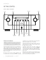
Front-panel
controls/indicators
NOTE:
For complete information about the functions of
the front-panel controls and their settings parameters,
see the
N
0
585 User Guide. at www.marklevinson.com.
Select knob: Rotate this knob to select the desired input to
send to the Speaker outputs and Line outputs. The name
and volume level of the selected input are indicated on the
Front-Panel display. (Note: The Select knob will bypass any
input for which the Input Name Setup menu parameter has
been set to “Unused.”)
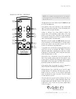
IR receiver: The IR receiver receives commands from
the included remote control when the N
0
585 is not being
controlled via its rear-panel IR Input connector (see
Rear-
Panel Overview, page 7, for more information).
Polarity button and LED: Pressing this button inverts the
absolute polarity of the signal. The LED illuminates when
the signal's polarity is inverted.
Setup button and LED: Press this button to display the
Setup menu, which you can use to customize the N
0
585 to
suit your other system components, individual preferences
and listening space. The Setup LED lights when the Setup
menu is active.
Enter button: Press this button to select or deselect a menu
item when the Setup menu is displayed. The Enter button
does not function during normal operation.
Standby
Button
and LED
Volume
Knob
Mute Button
and LED
Display
Intensity
Button
Setup Button
and LED
Polarity Button
and LED
Enter
Button
Balance
Button and
LED
Front-Panel
Display
IR
Receiver
Select
Knob
Summary of Contents for ?585
Page 1: ...INTEGRATED AMPLIFIER QUICK START GUIDE N0 585...
Page 2: ......


