


8
N
0
585 INTEGRATED AMPLIFIER
/
QUICK-START GUIDE
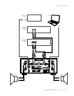
Ethernet port: This port supports connection to a home
network. For information on how to configure and use the
Ethernet port, see the
N
0
585 User Guide.
IR input connector: This connector accepts IR (infrared)
control signals from other equipment.
RS-232 port: This RJ-11 connector provides serial control
through a standard RS-232 connection.
Trigger output connector: This 3.5mm tip/sleeve connector
can be used to activate other components in the audio
system and listening room, such as amplifiers, lights and
window shades. A 12V 100mA DC signal is output whenever
the N
0
585 is on. (See illustration below.)
Trigger input connector: This 3.5mm tip/sleeve connector
can be connected to the trigger output of another system
component or control system that supplies a trigger
voltage. Whenever the N
0
585 detects a voltage between
5V and 12V DC at this connection it will turn On; when the
trigger signal at this connection ceases the N
0
585 will enter
the Standby mode. (See illustration above.)
AC Mains connector: This connector provides AC power to
the N
0
585 when the supplied power cord is connected from
it to an AC electrical outlet.
You should unplug the N
0
585 from the AC wall outlet during
lightning storms and extended periods of non-use.
Power switch: this mechanical switch turns the N
0
585's
power supply on or off. During normal operation, do not use
the Power switch to power off the N
0
585. Instead, use the
Standby button to place the N
0
585 into Standby.
GETTING STARTED
Summary of Contents for ?585
Page 1: ...INTEGRATED AMPLIFIER QUICK START GUIDE N0 585...
Page 2: ......


