background image

9

CARBONATION PUMP

The device is equipped with a carbonation pump required for the addition of Carbon Dioxide in the water. 

After about 3.5 minutes 

of continuous operation the pump stops carbonation

. Stops and starts dictated by the carbonation level probes can be a 

symptom of a leak in the water feed. To reset this simply disconnect and then reconnect the power to the equipment. 

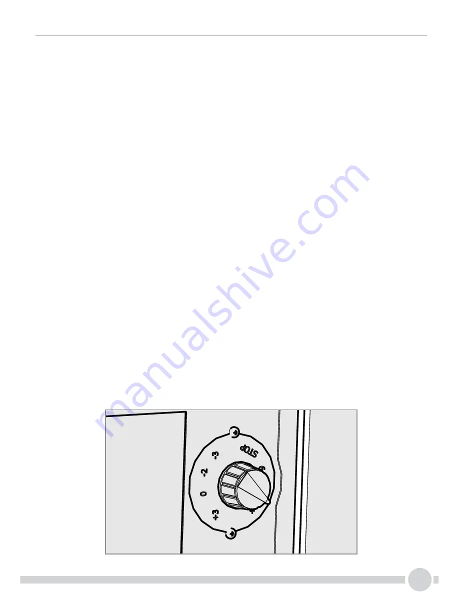
THERMOSTAT SETTING

The temperature of the dispensed beverages can be adjusted using the thermostat on the back of the chiller.

If the knob is turned in a clockwise direction the water will be cooler, if turned in the opposite direction water will be less cool. If the 

thermostat knob is turned completely anticlockwise (to “0” or “STOP” position), the compressor turns off.

4. OPERATING

4.1 BEFORE USING CHILLER

•Before connecting the appliance to the power source, let it stand upright for approximately 2 hours. This will reduce the possibility 

of a malfunction.

•Check that all installation procedures have been carried out.

•Ensure water inlet is open.

•Before supplying power to the unit check water and Carbon Dioxide lines do not leak.

•Plug the chiller into a suitable socket switch ON/OFF switch on the rear of the chiller to ON position.

•The “Power ON Status” light will light-up.

•When the unit is on, the carbonation pump starts to fill. The carbonation device stops when it reaches the maximum level.

•Once water and CO2 are connected, open the vent on top of the Chiller by pulling the ring. This operation allows the escape of any 

air bubbles present inside, which would affect the carbonation adversely.

•On the pressure reducer knob, adjust CO2 pressure to a value between 50 and 65 PSI (350 and 450 kPa) (3.5 - 4.5 bar)

This value depends on the temperature of the water and on the ambient temperature. The temperatures correspond to the CO2 

pressure.

•To enable filling the lines, open the two lines in the following order: cold sparkling water and cold natural water, until the flows appear 

regular and without the presence of air, in each case deliver and discharge at least 5 liters of water from each line.

•At this point you can dispense water.

Summary of Contents for FRIIA

Page 1: ...1 Instruction Manual Machine P N 1000864 1000865 FRIIA...

Page 2: ...ler to Boiler Cable 1501180 1m length 3 8 Tube water 1800627 1m length 6mm Tube CO2 1800628 User Manual n a It is highly recommended to fit a water regulator to the supply feed In the event of mechani...

Page 3: ...ment in good working order and do not allow any modifications unless authorised by the manufacturer This document shall be applied to equipment intended for the EC market only Introduction A Model Num...

Page 4: ...ollowing safety symbols to draw the operator s attention to all operations which must be strictly observed in order to prevent injury to persons or damage to the equipment DANGER Shows the existence o...

Page 5: ...conditions specified in the safety regulations in force CAUTION ELECTRICAL REQUIREMENTS The electrical circuit must be correctly earthed and connected by means of a suitable differential safety break...

Page 6: ...force in the country of use WARNING WATER SUPPLY Connect the water dispenser exclusively to a line of drinkable water supply WARNING WATER SUPPLY In order to avoid accidental flooding due to losses t...

Page 7: ...parating carton from plastic parts Always check that the equipment that is delivered corresponds to the model indicated in the accompanying document The equipment is shipped in a cardboard box Once th...

Page 8: ...equipment and located in such a way the power cable and water hose do not form an obstruction The appliance must not be installed where water jets can be generated Do not spray water on the device th...

Page 9: ...allation procedures have been carried out Ensure water inlet is open Before supplying power to the unit check water and Carbon Dioxide lines do not leak Plug the chiller into a suitable socket switch...

Page 10: ...sure values set on the pressure reducer then fully close the bottle with the valve 2 Remove the pressure reducer or disconnect the high pressure hose from the bottle if fitted Check the condition of t...

Page 11: ...cartridge with a sanitizing filter recommended by Marco and fill with clean water and with sanitizing fluid in the concentration and contact time recommended by the manufacturer 3 Disconnect the water...

Page 12: ...12 6 Troubleshooting Contact Marco service...

Page 13: ...369 437 600 600 100 min 275 200 Applies to model s 1000850 1000851 where is blank or one or more alphanumeric characters DRAWN BY DWG NO PANEL REMOVAL DESCRIPTION PJT 20 08 14 187 C O FRIIA Assembly...

Page 14: ...14 105mm 4 32mm 1 82 5mm Scale 1 1 For drip tray only 100mm NOTE Check scale of template before cutting Scale should be 1 1 FRIIA Font Counter Cut Out Check scale of template before cutting...

Page 15: ...15 Recommended Plumming...

Page 16: ...16 Power cord socket Power switch Thermostat control water in 3 8 CO2 connection 8mm tube Cold CO2 water out 1 4 CO2 pressure release valve Chiller Installation...

Page 17: ...17 Boiler Installation 1 2 3 4...

Page 18: ...Font Installation 32mm 1 1 No Drip Tray 130 500mm 1 3 0 5 0 0 m m 50mm Hosing should be trimmed to ensure continuous drop from font to boiler 100mm 18...

Page 19: ...1 105mm 4 2 Drip Tray sold seperately p n 2300268 130 500mm 1 3 0 5 0 0 m m 50mm Hosing should be trimmed to ensure continuous drop from font to boiler 100mm The drain outlet to the drip tray should...

Page 20: ...20 Connecting Hoses COLD HOT VENT POWER Chiller to boiler connector Vent Hot Water Cold Water Power 7mm 8mm HOT VENT COLD POWER CHILLER TO BOILER CONNECTION COLD...

Page 21: ...ce Panel 2 3 1 7 6 5 4 Set Up Single Button Font default is 3 button font Off Off Descale weeks Filter Litres Set Pin Next 2 3 UC MIX BOTH C Factory preset Mode Temp Units Next 6 85 183 5 C Factory pr...

Page 22: ...n Ventilation grilles cut in base panel and base plinth a grille must also be cut out at the top of the cabinet Please Note In all cases remove the back panel from the cabinet 50 65 265 The cabinet ma...

Page 23: ...23 Marco Beverage Systems Limited 74 Heather Road Sandyford Business Park Dublin 18 Ireland Tel 00353 0 1 295 2674 Email sales marcobeveragesystems com...

Reviews: