background image

ENGLISH

8

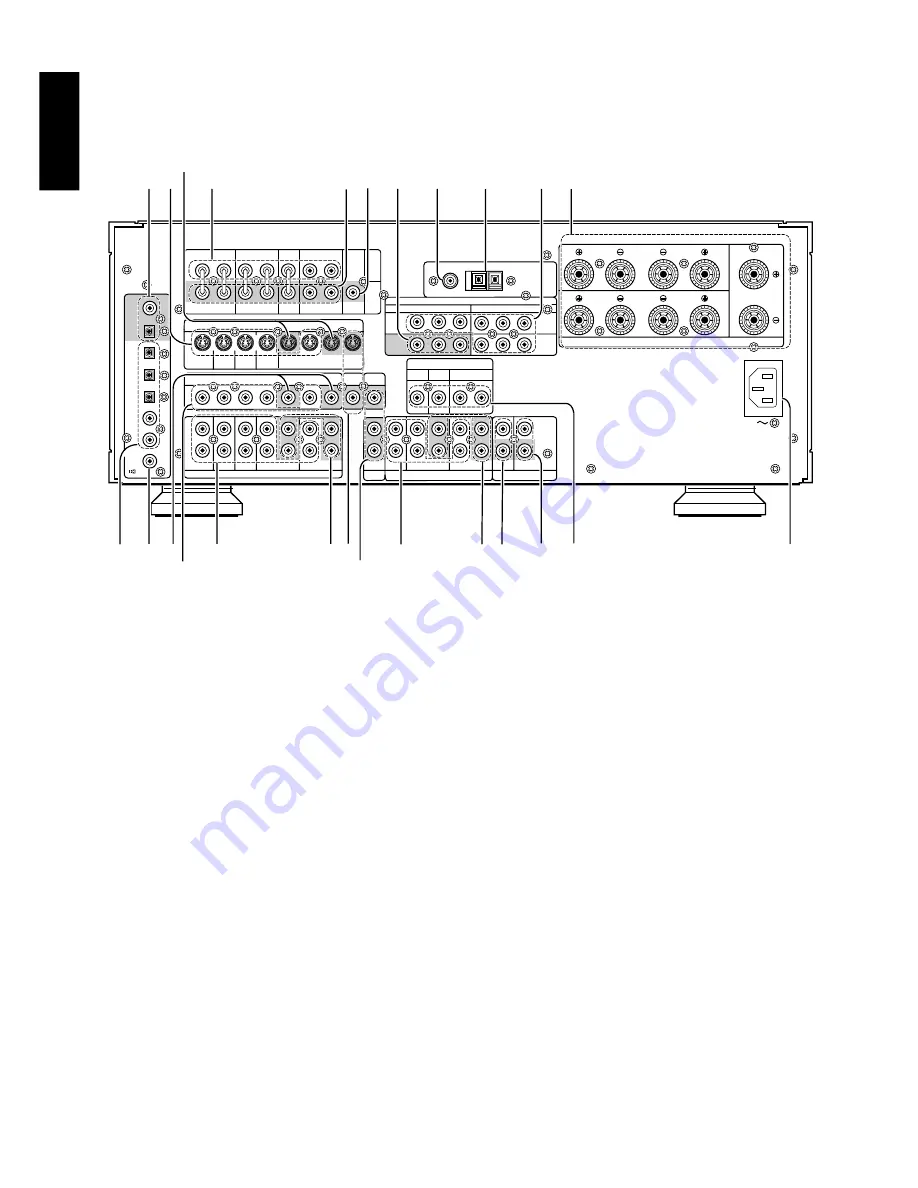
REAR PANEL CONNECTIONS

All connections to the rear panel should be made with the entire
system powered off.
To avoid errors, it is advisable to connect one cable at a time between
the various components.

7

6-Channel Inputs

If an external digital audio decoder is used, connect the outputs of
that decoder to these jacks. Note that front L&R channels are
common used in analog audio inputs, use the assigned input in OSD
setup menu system.
(See page 16 “System setup 1/2”.)

8

Five video inputs

TV,LD,DVD, VCR1, and DSS/VCR2 :

Connect each input to the video outputs of your video source
equipment.

9

Two video outputs

VCR1, and DSS/VCR2 :

Connect each output to the video input (REC in) of your video
recording equipment.

10 Five S-video inputs

TV,LD,DVD, VCR1,and DSS/VCR2 :

Connect each input to the S-video outputs of your video source
equipment.

11 Two S-video outputs

VCR1, and DSS/VCR2 :

Connect each output terminals to S-video input (REC in) of your video
recording equipment.

12 Monitor. (VIDEO/S-VIDEO) output jacks

Connect this jack to the composite or S-Video input of a TV monitor or
video projector to view the on-screen menus and the output of any
standard video source selected by the receiver’s video switcher.

AC INLET

AC INLET

AUDIO

AUDIO

REMOTE CONTROL

VIDEO

COAX

COAX

OUT

OUT

OPT

OPT
OUT

OUT

DIG .1

DIG .1

IN

DIG .2

DIG .2

IN

MULTI

ROOM

DIG .4

DIG .4

IN

IN

DIG .5

DIG .5

IN

IN

DIG .6

DIG .6

/

S - VIDEO

COMPONENT VIDEO

ANTENNA

FM (75

FM (75

)

GND

GND

AM

AM

RF IN

RF IN

L

R

TV

LD

DVD

IN  – VCR1 –  OUT

IN 

IN – DSS/VCR2 

 DSS/VCR2 – OUT

 OUT

TV

LD

DVD

MONI.

VCR1

VCR1

DSS / VCR2

DSS / VCR2 DSS / VCR2

DSS / VCR2

S2 IN

S2 IN

S2 IN

S2  IN

S2 IN

S2 OUT

AUDIO

AUDIO

CD

IN  – TAPE –  OUT

IN 

IN – CD-R / MD 

 CD-R / MD – OUT

 OUT

IN

OUT

REMOTE

MULTI

Y

Cr

Y

Cr

DSS

DSS

/ VCR2

/ VCR2

IN

DVD

DVD

IN

IN

L

R

L

R

FRONT

FRONT

SURROUND

SURROUND

S P E A K E R         S Y S T E M S         8     O H M S

S P E A K E R         S Y S T E M S         8     O H M S

DIG .3

DIG .3

IN

R

L

L

FRONT

R

L

R

(FRONT)

SURROUND

R

WOOFER

 SUB

R

L

MAIN

IN

OUT

PRE

SURROUND

FRONT

L

SURROUND BACK

L

R

CENTER

OUT

OUT

WOOFER

 SUB 

DIRECT IN

CENTER

SURROUND

R

L

MONI.

ROOM

MULTI 

MONITOR

OUT

IN

VCR1

CENTER

21 10

11

18

14

1

2

13

22

17

16

19

20

9

5

6 12

3

4 23

24

7

25

15

8

1

FM antenna terminal (75 ohms)

Connect an external FM antenna with a coaxial cable, or a cable
network FM source.

2

AM antenna and ground terminals

Connect the supplied AM loop antenna. Use the terminals marked
“AM” and “GND”.  The supplied AM loop antenna will provide good
AM reception in most areas.  Position the loop antenna until you hear
the best

3

Three analog audio inputs

CD, TAPE, and CD-R/MD :

Connect the audio outputs of your source components to the input
jacks on the receiver.

4

Two analog audio outputs for audio
source equipment

TAPE and CD-R/MD :

Connect each output to the audio inputs (REC in) of your recording
equipment.

5

Five analog audio inputs for video
source equipment

TV,LD,DVD, VCR1, and DSS/VCR2 :

Connect each input to the audio outputs of your video source
equipment.

6

Two analog audio outputs for video
source equipment

VCR1, and DSS/VCR2 :

Connect each output to the audio inputs (REC in) of your video
recording equipment.

Summary of Contents for SR-14mkII

Page 1: ...Model SR 14mkII User Guide AV Surround Receiver R...

Page 2: ...ro o se ponga en contacto con Marantz IMPORTANTE Cuando solicite el servicio otorgado por la garantia el usuario tiene la responsabilidad de demonstrar cu do efectu la compra En este caso su recibo de...

Page 3: ...Italiano Perch l unit possa essere sempre ben ventilata non installarla in scaffali o librerie e tenere presente quanto segue Non toccare la parte superiore del rivestimento durante il funzionamento...

Page 4: ...UB R L MAIN IN OUT PRE SURROUND FRONT L SURROUND BACK L R CENTER OUT OUT WOOFER SUB DIRECT IN CENTER SURROUND R L MONI ROOM MULTI MONITOR OUT IN VCR1 CENTER L R AUDIO OUT VIDEO OUT S VIDEO OUT L R AUD...

Page 5: ...OUND BACK SURROUND BACK L R CENTER CENTER OUT OUT OUT OUT WOOFER SUB DIRECT IN CENTER SURROUND R L MONI MONI ROOM ROOM MUL MULTI TI MONITOR OUT IN VCR1 CENTER OUT IN L R L R OUT IN L R L R NORMAL INPU...

Page 6: ...ER WOOFER SUB SUB R L MAIN MAIN IN OUT OUT PRE PRE SURROUND SURROUND FRONT FRONT L SURROUND BACK SURROUND BACK L R CENTER CENTER OUT OUT OUT OUT WOOFER SUB DIRECT IN CENTER SURROUND R L MONI MONI ROOM...

Page 7: ...30 CHANNEL MUTE VOLUME q w e r t y u i o 0 1 2 3 4 6 7 8 1 3 z x c n b v 2 9 0 5 RC5000i iv...

Page 8: ...STEM 13 OSD MENU SYSTEM 14 SPEAKERS SETUP AND LEVELS SETUP 14 ON SCREEN DISPLAY INFOMATION 17 BASIC OPERATION 18 LISTENING TO THE TUNER 18 RDS OPERATION FOR S VERSION ONLY 19 PLAYBACK OPERATION 20 OTH...

Page 9: ...s should have a value of 13A If a plug without a fuse is used the fuse at the distribution board should not be greater than 5A Note The severed plug must be destroyed to avoid a possible shock hazard...

Page 10: ...ter environment THX need not be activated for music movies made especially for TV or shows such as sports programming talk shows etc This is because they were originally mixed for a small room environ...

Page 11: ...dditional surround modes HDCD decoding capability to deliver the full sonic benefits of HDCD encoded CDs from a standard non HDCD CD player when connected to the SR 14mkII via the player s digital out...

Page 12: ...that have a monaural sound track S Source DIRECT In the source direct mode the tone control circuit and bass management configuration are bypassed for full range frequency response and the purist aud...

Page 13: ...rning the GYRO TUNING knob The Auto scan function starts when the GYRO TUNING knob is stopped 8 PRESET BUTTON Press this button to display the preset number The preset number is changed by turning the...

Page 14: ...hen the Sleep function is in use 7 Copy Indicators This indicator lights when VCR1 COPY TAPE COPY or DIGITAL COPY system is active 8 Night Mode Indicator This indicator lights when the SR 14mkII is in...

Page 15: ...75 FM 75 GND GND AM AM RF IN RF IN L R TV LD DVD IN VCR1 OUT IN IN DSS VCR2 DSS VCR2 OUT OUT TV LD DVD MONI VCR1 VCR1 DSS VCR2 DSS VCR2 DSS VCR2 DSS VCR2 S2 IN S2 IN S2 IN S2 IN S2 IN S2 OUT AUDIO AU...

Page 16: ...Optical Dig 4 5 Coaxial Connect the digital output from a DVD player HDTV receiver LD player or CD player to these jacks The signal may be either a Dolby Digital signal DTS signal or a standard PCM d...

Page 17: ...ay the surround processor which is connected to the DIRECT IN JACKS A D button This button is used to switch between the analog input and the digital input Front input button This button is used to sw...

Page 18: ...buttons These buttons are used to switch between FM AM and LW mode of the tuner LW button is not available in SR 14mkII Seek buttons These buttons are used to change the frequency Preset P P buttons T...

Page 19: ...word length of the code it is receiving Due to the sensitivity of the receiving LED the RC5000i may also learn noise from fluorescent lights etc which can quickly fill up the memory of the RC5000i In...

Page 20: ...L B 0 S L S L 1 0 1 f t R 1 0 1 0 SW 0 B S R 1 0 R 0 S B 0 E 1 E X I R U N T E R N T E R T S O L S E S C 0 L V D F E M E T U E T S S T T E 1 2 L L T E B 0 L S L S 0 O F M P AN UA R 0 S W 0 S R R 0 0 B...

Page 21: ...D LEVELS SETUP SPEAKERS SETUP Speakers size The first few adjustments tell the SR 14mkII which type of speakers are in use This is important as it adjusts the settings that determine which speakers re...

Page 22: ...the TEST TONE ON TEST TONE Press the ok button ON is indicated and the test tone starts from the front left speaker Notes Master volume level will be automatically set at the 0 dB position Level adju...

Page 23: ...signed as the desired source Use this menu to set the SR 14mkII for connected equipment and type of connection Example When the digital output of a DVD player is connected to Digital 4 input jack of t...

Page 24: ...on screen display which can be activated by the Main unit or remote appears on the TV screen to show the current setting status of the SR 14mkII These are available when OSD INFO setup is selected ENA...

Page 25: ...d frequency band 3 Press the AUTO TUNING button 7 on the SR 14mkII to display the frequency 4 Turn the GYRO TUNING knob 1 on SR 14mkII or press button on page of Control mode on the remote 5 If FM is...

Page 26: ...he display to indicate that the specified preset number has been cleared STATION NAME PRESET The station name preset function allows the name of each preset channel to be entered using alphanumeric ch...

Page 27: ...conds PLAYBACK OPERATION NORMAL PLAYBACK 1 Press the POWER ON button on the remote 2 Turn the INPUT SELECTOR 5 on the front panel or press the FUNCTION buttons on page of Input mode on the remote unit...

Page 28: ...ontrol unit and receiver MULTI ROOM SELECTOR OPERATION 1 Press the MULTI button 9 The unit enters multi room mode and the display indicates SELCT SOURCE and flashes the MULTI indicator for approx 10 s...

Page 29: ...um like atmospheres Select as your taste desires Note PCM audio signals can be processed in this mode when sampling frequency is 32 kHz 44 1 kHz or 48 kHz The 96 kHz sampling frequency mutes output 5c...

Page 30: ...3 2ch 2 DIGITAL DOLBY Pro Logic L R AC 3 2ch Lt Rt 2 DIGITAL 2 SURROUND DOLBY Pro Logic L R S AC 3 EX 2 DIGITAL DOLBY D EX L C R SL S SR LFE 96kHz PCM PCM DOLBY D 96kHz L R PCM audio PCM DOLBY Pro Log...

Page 31: ...h Lt Rt 2 DIGITAL 2 SURROUND STEREO L R S AC 3 EX 2 DIGITAL STEREO L C R SL S SR LFE 96kHz PCM PCM STEREO 96k L R PCM audio PCM STEREO L R PCM HDCD PCM STEREO L R Analog ANALOG STEREO DTS 5 1ch dts ST...

Page 32: ...med station when the PRESET button is pressed Nothing appears on the remote commander display Control with the remote control unit fails No sound is output from the surround back speaker Can not decod...

Page 33: ...HOW TO RESET THE UNIT Should the operation or display seem to be abnormal reset the unit with the following procedure The SR 14mkII is turned on press and hold the CL CLEAR o and DISPLAY OFF 0 buttons...

Page 34: ...20 kHz 8 ohms 140 W Ch Surround 20 Hz 20 kHz 8 ohms 140 W Ch THD Front 20 Hz 20 kHz 8 ohms 0 05 Input Sensitivity Impedance Linear 350 mV 47 Kohms Signal to Noise Ratio Linear 106 dB Frequency Respons...

Page 35: ...ati 23 20052 Monza Milano Italy Servizio Consumatori 1678 20026 Numero Verde IVORY COAST Hifivoir B P 2428 Abidjan 01 Ivory Coast JAPAN Marantz Japan Inc 35 1 Sagami Ohno 7 Chome Sagamihara shi Kanaga...

Reviews: