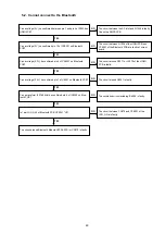
The circuit around CX870 is faulty.
YES
YES
YES
YES
YES
YES
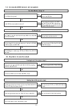
Can an output voltage (3.3V) to
U1070(DC-DC Conv.) be confirmed?
Can an output voltage (3.3V) to
Q1071(FET_SW) be confirmed?
Can an output voltage (1.2V) to U1067
be confirmed?
Can an output voltage (1.9V) to U1069
be confirmed?
Are the versions of the Ethernet SBL and IMG displayed in Version
Check Mode?
Can a voltage (5V) be confirmed between pin 2 and pin 5 of
N1029?
Is D5V_POWER (U1018 uCOM 85pin)
"Hi" ?
Is E_POWER1 (U1018 uCOM 53pin)
"Hi" ?
Is E_POWER4 (U1018 uCOM 53pin)
"Hi" ?
Is E_POWER2 (U1018 uCOM 54pin)
"Hi" ?
The circuit of D5V_POWER between
U1018 and U1070 are faulty.
The circuit of E_POWER1 between
U1018 and Q1071 are faulty.
The circuit of E_POWER4 between
U1018 and Q1071 are faulty.
The circuit of E_POWER2 between
U1018 and U1069 are faulty.
The circuit around U1070(DC-DC.
Conv.) is faulty.
The circuit around Q1071(FET_SW) is
faulty.
The circuit around U1067(DC-DC.
Conv.) is faulty.
The circuit around U1069(DC-DC.
Conv.) is faulty.
The Ethernet software is faulty.
The circuit between the AC inlet and N1029
is faulty. Check the SMPS PCB.
NO
NO
NO
NO
NO
NO
NO
NO
NO
NO
YES
YES
YES
YES
88
Summary of Contents for NR1605/FB
Page 8: ...Personal notes 8 ...
Page 26: ...Personal notes 26 ...
Page 103: ...CX870 7P 8P 5P PLATE PLATE 2P 7P 4P 7P 11P 5P 8P PLATE S30SC6MT WIRING DIAGRAM 103 ...
Page 140: ...Personal notes Personal notes 140 ...
Page 161: ...2 FL DISPLAY FLD 018BT021GINK FRONT U4400 PIN CONNECTION GRID ASSIGNMENT q T7 161 ...
Page 162: ...ANODE CONNECTION 162 ...


