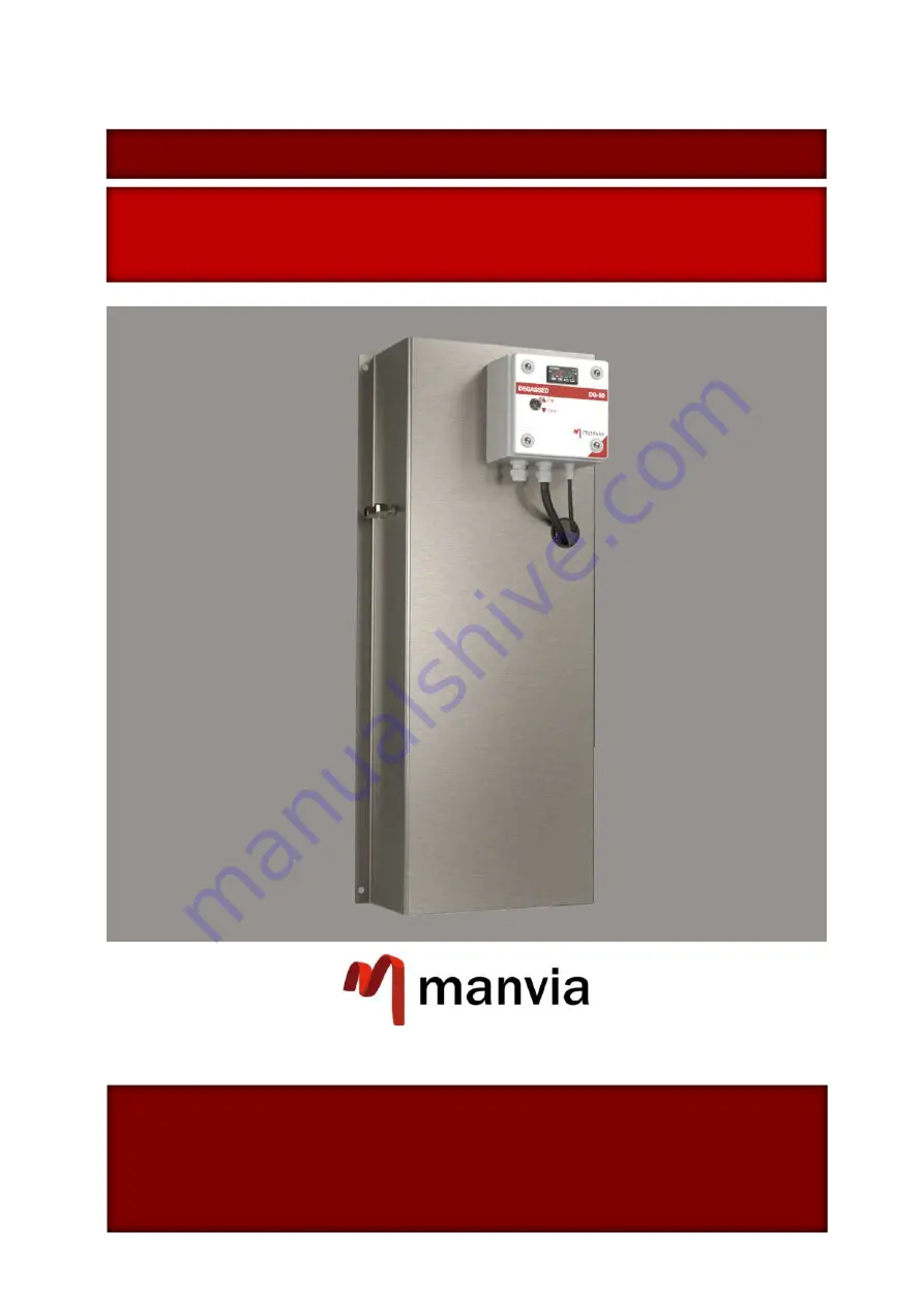
DEGASSING SYSTEM DG-50
INSTALLATION OPERATION & MAINTENANCE MANUAL
INSTALLATION, OPERATION &
MAINTENANCE MANUAL
MANVIA SAMPLE DEGASSING SYSTEMS
MANVIA ESPAÑA
Camino Fontán Porceyo 590
33392 - Porceyo
Asturias - España
(+34) 984 20 45 49
[email protected]
www.analyzersmanvia.com
SAMPLE DEGASSING SYSTEM DG-50


