Manitowoc Grove RT765E-2 Service And Maintenance Manual Download Page 68

HYDRAULIC SYSTEM

RT765E-2 SERVICE MANUAL

2-30

Published 9-04-2014, Control # 422-08

VALVES

General

This subsection provides descriptive information for several
of the main hydraulic valves used on this crane. For a listing
of the valves, the circuit they are used in, and their physical

location, refer to Table 2-3. Refer to Figure 2-17 and
Figure 2-18 for valve locations. 

The description of each valve given here is for the valve
itself. For information on how each valve functions in the
individual circuits, refer to the description and operation
procedures of that circuit.
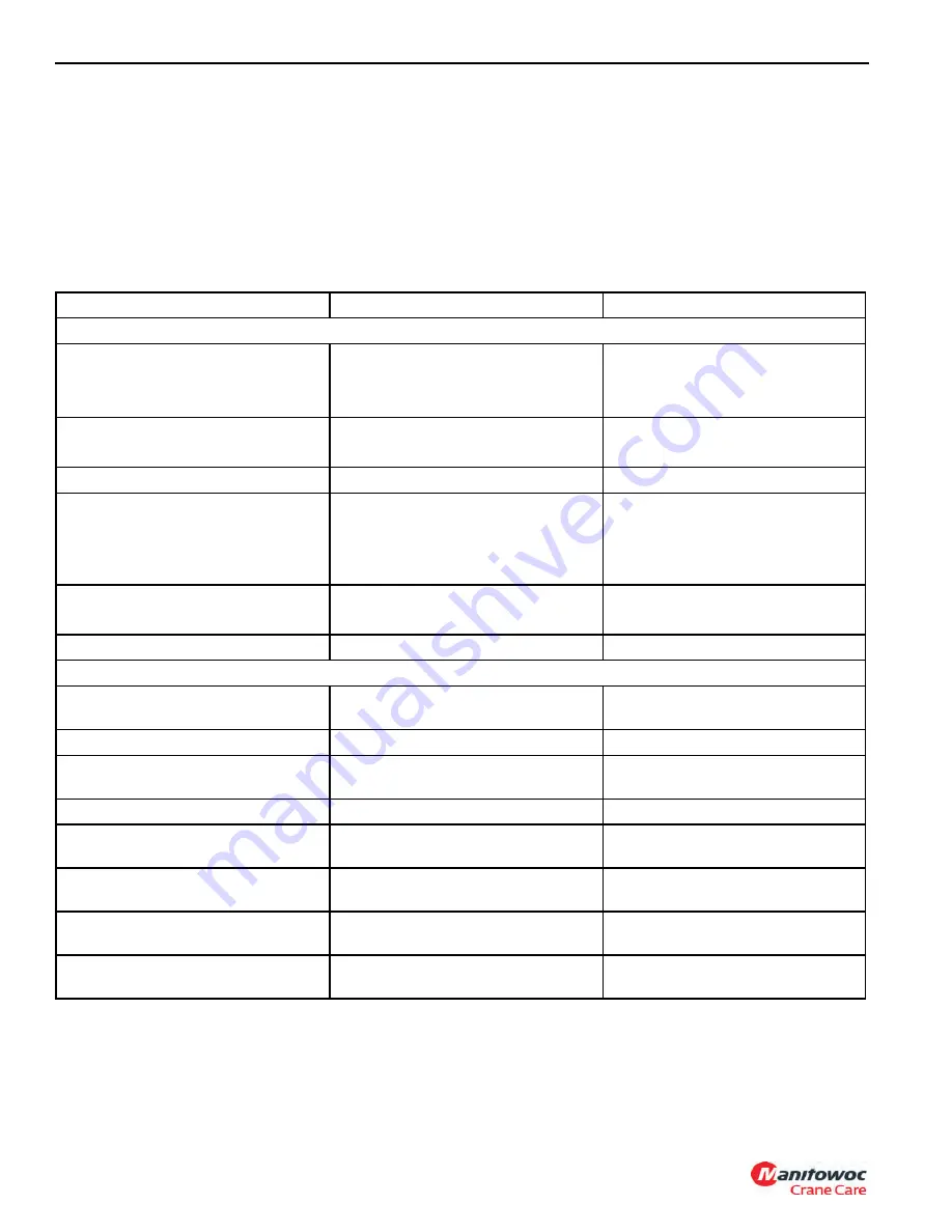
Table 2-3
Valve Usage Table

Valve Name

Circuit Used In

Physical Location

Superstructure

Directional Control Valves

Hoist/Lift /Telescope

Swing/Steer

Counterweight Removal (Optional)

Superstructure (Right Side)

Superstructure (Right Side)

Rear Turntable

Hydraulic Remote Controllers 
(Joysticks)

Hoist/Lift

Swing/Telescope

Right Armrest

Left Armrest

Dual Accumulator Charge Valve

Service Brakes

Superstructure (inside left side)

Swing Brake/Armrest Lockout Manifold

• Swing Brake Release

• Crane Function

Swing

Each hoist, swing, lift and telescope 
controller circuit

Superstructure (right side)

Superstructure (right side)

Holding Valves

Lift

Telescope

Lift cylinder (bolt on)

Telescope cylinder port blocks

Boom Lock Valve

Telescope

Telescope Cylinder Retreat Circuit

Carrier

Integrated Outrigger/Rear Steer Valve

Outrigger and Rear Steer

On front face of carrier frame front 
cross member

Outrigger Control Manifold

Outrigger

Front and Rear Outrigger Boxes

Axle Lockout Valve (Double Solenoid 
Valve)

Rear Axle Lockout

On carrier left side rear center frame 
cross member

High Speed Boost Selector Valve

Hoist and Telescope

On swivel port #6

Priority Flow Control Valves

Hydraulic Oil Cooler, Transmission Oil 
Cooler, Fan Motor

On carrier, RH frame rail

Priority Flow Control Valves

Service Brake and Air Conditioner 
Circuit

On carrier, LH frame rail

Cross Axle Differential Lock Solenoid 
Valve

Optional axle differential lock

On carrier front side rear center frame 
cross member

Axle Disconnect Solenoid Valve

Two/Four Wheel Drive

On carrier front side rear center frame 
cross member

Reference Only

Summary of Contents for Grove RT765E-2

Page 1: ...Service Maintenance Manual Grove RT765E 2 R e f e r e n c e O n l y ...

Page 2: ...R e f e r e n c e O n l y ...

Page 3: ...ched to the operator s cab Always furnish crane serial number when ordering parts or communicating service problems with your distributor or the factory An untrained operator subjects himself and others to death or serious injury Do not operate this crane unless You are trained in the safe operation of this crane Manitowoc is not responsible for qualifying personnel You read understand and follow ...

Page 4: ...e State of California to cause cancer birth defects and other reproductive harm CALIFORNIA PROPOSITION 65 WARNING Battery posts terminals and related accessories contain chemical lead and lead compounds chemicals known to the State of California to cause cancer birth defects or other reproductive harm Wash hands after handling R e f e r e n c e O n l y ...

Page 5: ...ine 1 3 Axles 1 3 Brakes 1 3 Wheels and Tires 1 3 Swing Gearbox 1 3 Boom 1 3 Swivel Assembly 1 3 Hydraulic Pumps 1 3 Hoists 1 4 Crane Nomenclature 1 7 General Maintenance 1 9 Cleanliness 1 9 After Cleaning 1 9 Removal and Installation 1 9 Disassembly and Assembly 1 9 Pressing Parts 1 10 Locking Devices 1 10 Wires and Cables 1 10 Shims 1 10 Hoses and Tubes 1 10 Bearings 1 11 Gaskets 1 11 Batteries ...

Page 6: ...dures 2 12 Hydraulic Oil Return Filter Assembly 2 13 Fill Cap Breather 2 13 Oil Cooler 2 15 Description 2 15 Oil Temperature Switches 2 15 Hydraulic Pumps 2 17 Description 2 17 Maintenance 2 17 Pump Disconnect Assembly 2 21 Disassembly 2 21 Assembly 2 21 Pressure Setting Procedures 2 23 Procedure A Main Control Valve Reliefs 2 24 Procedure B Main Directional Control Valve Pilot Supply Pressure 2 2...

Page 7: ... 53 Description 2 53 Maintenance 2 53 High Speed Boost Selector Valve 2 54 Description 2 54 Maintenance 2 54 Hydraulic Accumulator 2 55 Description 2 55 Maintenance 2 55 Service Brake and CAC Fan Motor Priority Flow Control Valve 2 56 Description 2 56 Maintenance 2 56 Oil Cooler Fan Motor Priority Flow Control Valve 2 57 Description 2 57 Maintenance 2 57 Telescope Cylinder Charge Valve Manifold If...

Page 8: ...g System Troubleshooting 3 9 Alternator Replacement 3 11 Starter Replacement 3 11 Battery Replacement 3 12 Relay Panel Component Replacement 3 12 Gauge Cluster Replacement 3 13 Rocker Switch Replacement 3 13 Ignition Switch Replacement 3 14 Turn Signal Lever and Transmission Shift Lever Replacement 3 15 Windshield Wiper Assembly Replacement 3 17 Windshield Washer Assembly Replacement 3 18 Skylight...

Page 9: ...gaway Boom Extension 4 24 Description 4 24 Maintenance 4 24 Description 4 32 Maintenance 4 32 SECTION 5 Hoist and Counterweight Description 5 1 Theory of Operation 5 1 Maintenance 5 2 Warm up Procedure 5 2 Hoist Area Access 5 2 Removal 5 4 Installation 5 4 Functional Check 5 4 Fluid Level 5 4 Usage and Inspection 5 5 Preventative Maintenance 5 5 Oil Sampling 5 7 Brake Test Procedure 5 7 Hoist to B...

Page 10: ... 6 10 Maintenance 6 10 Swivels 6 15 Description 6 15 Hydraulic Swivel 6 17 Description 6 17 Theory Of Operation 6 17 Maintenance 6 17 Two Port Water Swivel 6 19 Description 6 19 Maintenance 6 19 Electrical Swivel 6 20 Description 6 20 Theory of Operation 6 20 Maintenance 6 20 Swing Lock Pin 6 22 Description 6 22 Maintenance 6 22 360 Swing Lock Control Positive Lock Type Optional 6 22 Description 6...

Page 11: ...ory Of Operation 8 7 Maintenance 8 8 Rear Steering System 8 9 Troubleshooting 8 9 Hydraulic Pumps 8 10 Front Steering Control Valve 8 10 Integrated Outrigger Rear Steer Control Valve 8 10 Steer Cylinders 8 10 Rear Axle Oscillation Lockout System 8 11 Description 8 11 Theory Of Operation 8 11 Axle Oscillation Lockout Cylinders 8 13 Axle Oscillation Lockout Valve 8 13 Maintenance 8 13 Brake System 8...

Page 12: ...ication Intervals 9 1 Standard Lubricants 9 2 Arctic Lubricants and Conditions 9 3 Surface Protection for Cylinder Rods 9 6 Wire Rope Lubrication 9 6 lubrication Points 9 7 CraneLUBE 9 7 Safety 9 7 Steering and Suspension 9 8 Axles 9 10 Drive Train 9 12 Drive Train continued 9 14 Turntable 9 16 Outriggers 9 18 Boom 9 20 Hoist 9 26 Hydraulic 9 28 Carwell Rust Inhibitor 9 31 Protecting Cranes From R...

Page 13: ...uds 1 19 Wire Rope 1 20 General 1 20 Environmental Conditions 1 20 Dynamic Shock Loads 1 20 Lubrication 1 20 Precautions and Recommendations During Inspection or Replacement 1 20 Wire Rope Inspection Running Ropes and Pendant Cables 1 21 Wire Rope Inspection Boom Extension and Retraction Cables 1 22 Wire Rope Inspection Replacement All Wire Rope 1 22 Seizing Wire Rope 1 23 Installing 35x7 Class Wi...

Page 14: ...ll welded parallel box construction steel frame utilizing two drive steer axles Axle steering is accomplished utilizing hydraulic steer cylinders The engine is mounted at the rear of the crane carrier and provides motive power through a six speed forward and reverse transmission The outriggers are single stage double box telescopic beam type outriggers The superstructure is capable of 360 degree r...

Page 15: ...2 1 Charge Pump Capacity 20 gpm 76 l min 2000 rpm Transmission Gear Ratios Forward and Reverse Low Range 1st 12 59 2nd 6 06 3rd 2 22 High Range 4th 4 33 5th 2 08 6th 0 76 Engine Cummins QSB 6 7 Type 4 cycle Diesel Turbocharged Number of Cylinders 6 Horse Power Rating 179 kW 240 hp 2500 rpm Oil Pan Capacity 18 5 qt 15 6 l Coolant System 40 qt 38 l Axles Total Ratio 24 817 1 Carrier Ratio 5 86 1 Pla...

Page 16: ...ts Drum Dimensions Diameter 15 in 381 mm Length Standard 18 38 in 467 mm Cable Diameter 0 75 in 19 mm Length Main 650 ft 198 m Length Aux 653 ft 199 m Max Permissible Line Pull 6x36 16 800 lb 74 7 kN Max Single Line Speed 500 fpm 153 m min FIGURE 1 1 7919 R e f e r e n c e O n l y ...

Page 17: ...48013 Add To Basic Unit Weight 10 0 to 17 0 m 33 to 56 ft Bi Fold Boom Extension 652 58 256 92 1132 2495 1817 4006 685 1511 10 0 m 33 ft Fixed Boom Extension 726 24 285 92 782 1723 1397 3079 615 1356 Boom Extension Carrier Brackets Bolt On Bi fold Ext 548 64 216 00 133 293 180 396 47 103 Boom Extension Carrier Brackets Bolt On Fixed Ext 568 96 224 00 104 229 146 321 42 92 Auxiliary Boom Nose Insta...

Page 18: ...rweight 553 72 218 00 53 117 72 159 19 42 Sub Aux Hoist replace IPO Cwt with Aux Hoist and Cable 134 62 53 00 264 583 88 193 352 776 Rem Main Hoist Cable 153 m 502 ft of 3 4 in 35x7 66 04 26 00 278 612 45 99 323 711 Rem Aux Hoist Cable 153 m 502 ft of 3 4 in 35x7 149 86 59 00 278 612 103 226 380 838 Sub Optional Cable on Main Hoist 199 m 653 ft of 3 4 in 35x7 66 04 26 00 84 185 14 30 98 215 Sub Ti...

Page 19: ... 9 04 2014 Control 422 08 RT765E 2 SERVICE MANUAL INTRODUCTION 1 GROVE Crane Nomenclature FIGURE 1 2 7671 2 18 17 15 14 12 13 19 20 26 25 24 22 21 16 11 1 2 3 4 5 10 9 6 7 8 1 23 7671 1 12 R e f e r e n c e O n l y ...

Page 20: ...m Fixed Counterweight Units Only 8 Main Hoist 9 Auxiliary Hoist 10 Counterweight 11 Muffler 12 Outrigger Jack Cylinder 13 Battery Item Description 14 Fuel Tank 15 Crane Steps 16 Boom Pivot Pin 17 Hydraulic Valves and Swing Motor Cover 18 Swingaway Extension 19 Auxiliary Boom Nose 20 Job Extension 21 Outrigger Pads 22 Lift Cylinder 23 Front Axle 24 Hydraulic Fuel Tank 25 Rear Axle 26 Air Intake Cle...

Page 21: ...loth Make sure the parts are completely dry and clean DO NOT use compressed air on bearings Spinning bearings without lubricant will cause damage to the bearing and could cause the bearing to fly apart Removal and Installation When performing maintenance do not attempt to manually lift heavy parts when hoisting equipment should be used Never locate or leave heavy parts in an unstable position When...

Page 22: ...oper identification during assembly Shims When shims are removed tie them together and identify them as to location Keep shims clean and flat until they are reinstalled Hoses and Tubes Inspection Check hoses carefully Do not use your bare hands to check for leaks Tighten all connections to recommended torque If the hose end connections are damaged always replace the hose or tube Damaged dented cru...

Page 23: ...ract Installation Lubricate new or used bearings before installation Bearings that are to be preloaded must have a film of oil over the entire assembly to obtain accurate pre loading When installing a bearing spacer or washer against a shoulder on a shaft be sure the chamfered side is toward the shoulder When pressing bearings into a retainer or bore uniformly apply pressure to the outer race If t...

Page 24: ...or badly corroded fittings Fitting slippage on hose Other signs of significant deterioration If any of the above conditions exist evaluate hose assemblies for correction or replacement For replacement of hose assemblies refer to your Manitowoc Crane Care Parts Manual 2 At the same service interval visually inspect all other hydraulic components and valves for the following Leaking ports Leaking va...

Page 25: ...ed to seat the nut snugly against the fitting This is considered the Finger Tight condition 4 Using a permanent type ink marker make a mark on one of the flats of the nut and continue it onto the hex of the static fitting or port 5 Tighten the joint by the number of flats as specified in Table 1 3 and 1 4 for size and type of fitting 6 Optionally for future tightening of the same connection extend...

Page 26: ...ting Fitting to Port Refer to Table 1 5 for the following procedure 1 Make sure both threads and sealing surfaces are free of burrs nicks scratches or any foreign particles 2 Lubricate O ring with clean oil Figure 1 6 3 Turn fitting until finger tight 4 Using the assembly torque method tighten to given torque for size from Table 1 5 Table 1 5 Straight Thread Fittings Electrical System Harnesses Wi...

Page 27: ... axle and suspension mounting structures Hydraulic cylinder end connections The above is provided only as a guide and your inspection plan should not be limited to the areas listed A thorough visual inspection of all weldments is good practice Anyone requiring more detailed inspection instructions and or repair procedures may request same by contacting your local Manitowoc distributor Loctite Alwa...

Page 28: ...olerance Torque Wrenches Flexible beam type wrenches even though they might have a pre set feature must be pulled at right angle and the force must be applied at the center of the handle Force value readings must be made while the tool is in motion Rigid handle type with torque limiting devices that can be pre set to required values eliminate dial readings and provide more reliable less variable r...

Page 29: ... 9 0 7 7 19 17 32 30 52 48 78 72 114 106 156 144 270 249 416 384 606 560 813 751 1141 1053 2028 1865 8 12 5 11 5 26 24 48 44 73 67 120 110 161 143 234 216 385 355 615 567 929 857 1342 1234 2043 1885 3276 3024 Bolt Diameter Inches Torque Values Pounds Foot Maximum Minimum SAE Grade 1 4 5 16 3 8 7 16 1 2 9 16 5 8 3 4 7 8 1 1 1 8 1 1 4 1 1 2 Zinc Flake 5 8 15 28 44 66 95 132 229 364 543 785 944 1654 ...

Page 30: ...20 10 9 4 5 4 1 9 2 8 5 16 14 26 24 38 35 75 69 130 120 212 195 322 298 455 418 629 581 856 790 1089 1005 1591 1469 2163 1997 12 9 5 4 4 9 11 10 19 17 31 28 45 42 89 83 156 144 248 228 387 357 532 490 756 698 1029 949 1306 1206 1910 1763 2595 2395 Bolt Diameter Metric Torque Values Nm Class M8x1 M10x1 M10x1 25 M12x1 5 M14x1 5 M16x1 5 M18x1 5 M20x1 5 M22x1 5 M24x2 M27x2 M30x2 M33x2 M36x3 8 8 23 46 ...

Page 31: ...ss Steel Fasteners with Oil Lubrication NOTE Stainless steel fasteners tend to gall while being tightened To reduce this risk lubricate the threads with oil or molybdenum disulfide and torque at low speeds without interruptions Do not use excessive pressure Impact wrenches are not recommended Weld Studs Unless otherwise specified the following grade 2 torque values 10 apply Table 1 14 Weld Stud To...

Page 32: ...d as part of a maintenance program shall be compatible with the original lubricant and to this end the rope manufacturer should be consulted Lubricant applied shall be of the type which does not hinder visual inspection Those sections of rope which are located over sheaves or otherwise hidden during inspection and maintenance procedures require special attention when lubricating rope The object of...

Page 33: ...ection Running Ropes and Pendant Cables Wire rope should be inspected frequently daily and periodically yearly in accordance with the following information excerpted from a National Consensus Standard as referenced by Federal Government Agencies Recommended inspection intervals may vary from machine to machine and may vary based on environmental conditions frequency of lifts and exposure to shock ...

Page 34: ...length of the extension and retraction cables This inspection should be used to monitor progressive degradation and to discover severe damages necessitating wire rope replacement or equipment repair Inspection criteria are as follows Inspect for reduction of rope diameter below nominal diameter Inspect for severely corroded or broken wires at end connections Inspect for severely corroded cracked b...

Page 35: ...of the individual wires and strands at the ends All preformed and non preformed styles of wire rope should be seized prior to cutting Seizings must be placed on both sides of the point where the wire rope is to be cut The two preferred methods for seizing wire ropes are Method 1 Using a length of soft annealed wire Figure 1 11 place one end in the groove between two strands of the wire rope Turn t...

Page 36: ...th operation during its useful life Ideally you should run these loads with reeving that lets you place the loads on the block with all rope off the drum except the last three wraps If this is not possible alternate methods must be used to assure proper tensioning of the rope on the drum Procedures for Cutting and Preparing 35x7 Class Wire Rope 35x7 class rope is a special wire rope that must be h...

Page 37: ...1 25 Published 9 04 2014 Control 422 08 RT765E 2 SERVICE MANUAL INTRODUCTION 1 GROVE FIGURE 1 14 R e f e r e n c e O n l y ...

Page 38: ...INTRODUCTION RT765E 2 SERVICE MANUAL 1 26 Published 9 04 2014 Control 422 08 THIS PAGE BLANK R e f e r e n c e O n l y ...

Page 39: ...Charge Air Cooler Valve Relief Pressure 2 26 Procedure F Brake Dual Accumulator Charge Valve Pressure Limits 2 26 Procedure G Accumulator Pre Charge Pressure 2 26 Procedure H PreCharging The Accumulator 2 27 Procedure I Swing Valve Work Port Reliefs Pressure 2 27 Procedure J Front Steer Relief Valve Pressure 2 28 Procedure K Outrigger Rear Steer Valve Relief 2 28 Procedure L Hydraulic Oil Cooler F...

Page 40: ...lation Lockout Cylinder 2 75 Description 2 75 Maintenance 2 75 Steer Cylinder 2 78 Description 2 78 Maintenance 2 78 Outrigger Extension Cylinder 2 81 Description 2 81 Maintenance 2 81 Outrigger Jack Cylinder 2 84 Description 2 84 Maintenance 2 84 Counterweight Removal Cylinder 2 87 Description 2 87 Maintenance 2 87 DESCRIPTION This section describes the hydraulic system the components which make ...

Page 41: ...wo or more functions contained in one unit Pressure Transducer Hydraulic electrical located in lift cylinder circuit for cranes RCL circuit 1 2 1 2 2 1 1 2 Filter Removes contamination from hydraulic fluid Filter with Bypass Valve Bypass valve allows hydraulic fluid to bypass the filter if the filter becomes clogged Accumulator Used to either develop flow or absorb shock Check Valve Creates back p...

Page 42: ...unloader valve cartridge Closed Center Motor Spool Pressure compensated directional control valve for motor with open port for flow back to tank Allows flow back to tank when the crane is shut down Single Acting Cylinder Extended hydraulically and retracted with a spring Double Acting Cylinder Extended and retracted hydraulically Double Acting Telescope Cylinder Anchored rod pushes barrel out when...

Page 43: ... tighten the bolts at the rigid end the adjustable end and the mounting brackets After tubes are mounted install the hoses Connect both ends of the hose with all bolts finger tight Position the hose so it does not rub the machine or another hose and has a minimum of bending and twisting Tighten bolts in both couplings Due to manufacturing methods there is a natural curvature to a hydraulic hose Th...

Page 44: ...tion it will go 28 Connect the line to the swing motor then drive the swing motor in the opposite direction until the boom is centered and forward Replenish the reservoir hydraulic oil level as necessary When hydraulic oils are changed recheck the reservoir hydraulic oil level after brief system operation and add hydraulic oil as required Working reservoir capacity capacity to full mark is 150 U S...

Page 45: ...pairs External leaks sometimes develop at fittings and seals Spool seals are susceptible since they are subject to wear Seals may be damaged by temperatures that are too high or by dirt or paint accumulation on the spool Damaged or torn seals must be replaced A component functioning at reduced efficiency may indicate that the control valve for that component is leaking internally If preliminary ch...

Page 46: ...ssemblies are recommended to be replaced after 8000 hours of service life Working conditions ambient temperatures and high duty circuits can affect service life of hose assemblies and must be taken into account when inspecting and replacing hoses High duty circuits can include but are not limited to outriggers hoist s boom lift swing pump suction and discharge to directional valves and directional...

Page 47: ...c oil temperature condition The switch is normally closed and will open and cause the circuit to lose ground when the hydraulic oil temperature exceeds 190 F 88 C When the circuit loses ground the CAN bus system will turn on power to illuminate the Hydraulic Oil High Temperature Indicator in the gauge display in the operator s cab See Section 3 Operating Controls and Procedures in the Operator s M...

Page 48: ...The No 2 hydraulic pump supplies the front steer swing directional control valve A load sense flow divider located in the swing directional control valve ensures the front steer valve gets priority flow upon demand and the swing directional control valve gets any excess flow No 3 Pump The torque converter drives the No 3 pump The No 3 hydraulic pump supplies the service brake dual accumulator char...

Page 49: ...ve engine speed b Regulate engine speed c Air entering at suction lines c Check all lines for security and proper repair Tighten repair or replace as needed 4 Excessive pressure buildup a System relief valve set too high a Using adequate pressure gauge adjust system relief valve as necessary b Restricted pump to control valve supply line b Clean repair or replace line as necessary 5 Specific hydra...

Page 50: ...al inspection Look for a restriction in the linkages low level of hydraulic oil bent tubes collapsed or ballooned hoses leakage around the hydraulic components etc Second make an analysis of symptoms The function of each component in the system must be known before a correct analysis can be made Remember 1 If a problem is common to all circuits the component which is causing the problem must also ...

Page 51: ...e bypass valve attached to the cap for any damage replace if necessary 5 Remove and discard the O ring between the cap and the return filter head 6 Remove the element from through the return filter head Element Installation 1 Replace the filter with one having the same part number as the one removed Lube the O rings on both ends of the element and insert the element into the return filter head 2 I...

Page 52: ...2 08 7834 1 5 6 3 7 8 4 2 10 9 11 12 13 FIGURE 2 2 Item Description 1 Filter Head 2 Bowl w Extension 3 Gauge Assembly 4 Square O ring 5 Gasket 6 Element 7 Cap Item Description 8 O ring 9 Capscrew 10 Bypass Valve Assembly 11 Spacer 12 Capscrew 13 Washer R e f e r e n c e O n l y ...

Page 53: ... are installed in the return tube The two oil cooler fan motor temperature switches are normally closed at low oil temperatures When the hydraulic oil temperature reaches 120 F 48 9 C one of the oil cooler fan motor temperature switch will open causing the CANbus system to turn on the oil cooler fan motor to its low rpm setting When the hydraulic oil temperature reaches 180 F 82 2 C the other oil ...

Page 54: ... Published 9 04 2014 Control 422 08 FIGURE 2 3 5 1 2 3 6 7 4 7839 Item Description 1 Outlet Port 2 Fan Motor 3 Inlet Port 4 Drain Port Item Description 5 Temperature Switch 6 Transmission Oil Cooler 7 Hydraulic Oil Cooler R e f e r e n c e O n l y ...

Page 55: ...verter Remove the pump 5 Clean the gasket material from the drive pad on the torque converter and the pump 6 Cover the drive pad s opening to prevent dirt from entering No 1 Pump Installation 1 Clean the drive pad and the pump with Loctite cleaning solvent 7070 or similar non chlorinated solvent 2 Apply a light coating of Loctite primer N7649 to drive pad and pump mounting surface Allow primer to ...

Page 56: ...at properly on the drive pad 7 Route pump and its gasket on the studs Make sure the pump s splined drive shaft meshes with the pump disconnect assembly s splined coupler Press the pump and its gasket into place so they seat properly on the pump disconnect assembly 8 Secure pump drive assembly and pump to torque converter drive pad with nuts and washers Torque nuts refer to Fasteners and Torque Val...

Page 57: ...ure the reservoir is filled with the proper hydraulic fluid to the high level mark on the reservoir sight gauge 2 Ensure no air is entering the pump inlet and that the pump suction or inlet fluid is not bleeding back to the reservoir when the engine is stopped by making sure all suction or inlet lines are air tight 3 Remove all pump outlet hoses Fill pump outlet port of each pump section with as m...

Page 58: ...t is probably sucking air into its inlet keeping it from priming In case of abnormal noise stop engine and inspect the pump and the suction line for a loose connection a leak or a damaged or missing o ring 7 If the pump seems to be running properly increase the rpm to 1500 to 1800 rpm for one to two minutes while operating no hydraulic functions Repeat checks in steps 4 5 and 6 8 Increase engine s...

Page 59: ... 3 Pin collar to shaft with roll pin 4 Install shifter lock on handle 5 Install handle on free end of shaft Pin handle to shaft with roll pin 6 Adjust shifter lock so handle can lock it into the IN detent position and into the OUT detent position Then place handle at the OUT position 7 Pin shifter assembly to shaft with roll pin 8 Verify shifting parts shift properly In other words verify the hand...

Page 60: ...ntrol 422 08 7528 FIGURE 2 5 1 7530 2 6 9 10 3 4 8 5 11 2 7 Item Description 1 Pump Disconnect Assembly 2 Housing 3 Shaft 4 Oil Seal 5 Handle 6 Collar Item Description 7 Shifter Assembly 8 Shifter Lock 9 Roll Pin 10 Plug 11 Pipe Plug 12 Engine R e f e r e n c e O n l y ...

Page 61: ...on Load Sense Relief 4000 27 6 50 0 4 Main Control Valve Inlet Gauge Port Lift Down Relief 2000 13 8 700 0 4 8 0 Telescope Retract Relief 3500 24 1 50 0 4 Main Control Valve Telescope Retract Port Telescope Extend Relief 2700 18 6 50 0 4 Main Control Valve Telescope Extend Port Hoist Raise 3500 24 1 50 0 4 Main Control Valve Hoist Raise Port Hoist Lower 3500 24 1 50 0 4 Main Control Valve Hoist Lo...

Page 62: ...auge 4 Install pressure check diagnostic quick disconnect with gauge onto test nipple at main directional control valve load sense relief test port Figure 2 7 Disconnect Hoist Brake Release Line FIGURE 2 6 6659 1 Right Side View of Main Hoist FIGURE 2 7 6468 1 8 7 1 9 10 6 5 4 3 2 11 Item Description 1 Auxiliary Hoist Down Port Relief 2 Main Hoist Down Port Relief 3 Load Sense Relief Test Port 4 I...

Page 63: ...e load sense test port Procedure B Main Directional Control Valve Pilot Supply Pressure 1 Install pressure check diagnostic quick disconnect with gauge onto test nipple at pilot supply test port Figure 2 7 2 Disconnect the hoist brake release line at the main hoist Figure 2 6 Cap fitting and plug hose 3 While attempting to hoist down with the engine running at full rpm check the pilot supply press...

Page 64: ...5 when the valve stops charging The accumulator charge valve is non adjustable 4 With the engine running bleed off the hydraulic pressure stored in the accumulators by pushing the service brake pedal on the cab floor until the gauge reads about 1950 psi 13 4 MPa Listen to hear when the service brake dual accumulator charge valve starts to recharge Push the service brake pedal once more the valve s...

Page 65: ...bly bleed valve Without looping or twisting the hose attach the swivel nut to the accumulator gas valve and tighten to 10 to 15 lb in 1 1 to 1 7 Nm 5 Turn the gas chuck T handle all the way in clockwise which will depress the core in the gas valve 6 Crack open the nitrogen bottle valve and slowly fill the accumulator Shut off the valve when the pre charge pressure is 900 psi 50 0 6 2 MPa 0 4 0 7 I...

Page 66: ...ve to 2500 psi 50 17 2 MPa 0 4 3 Remove pressure gauge from the pressure check port Procedure L Hydraulic Oil Cooler Fan Motor Control Valve 1 Make sure that machine is up to operating temperature then unplug oil cooler valve solenoid located near oil cooler fan motor to assure fan is running at full speed 2 Run the engine at idle and using a photo tachometer adjust flow control valve until a fan ...

Page 67: ...rectional control valve load sense relief test port Figure 2 7 2 With engine at full rpm retract counterweight cylinder and set relief valve on counterweight valve Figure 2 16 to 1750 psi 50 12 1 MPa 4 turn in to raise or out to lower pressure 3 Remove pressure gauge from main directional valve FIGURE 2 15 Flow Control Valve Port CF Adjustable Relief Valve 7797 FIGURE 2 16 7532 3 Relief Valve R e ...

Page 68: ...e left side Swing Brake Armrest Lockout Manifold Swing Brake Release Crane Function Swing Each hoist swing lift and telescope controller circuit Superstructure right side Superstructure right side Holding Valves Lift Telescope Lift cylinder bolt on Telescope cylinder port blocks Boom Lock Valve Telescope Telescope Cylinder Retreat Circuit Carrier Integrated Outrigger Rear Steer Valve Outrigger and...

Page 69: ...arrier 5 7 Rear 9 Item Description 1 Front Outrigger Control Valve 2 Integrated Outrigger Rear Steer Valve 3 Fan Bypass Valve 4 Priority Flow Divider Valve 5 Adjustable Flow Valve Item Description 6 Park Brake Range Shift Valve 7 Differential Lock Valve Optional 8 Axle Lockout Valve 9 Rear Outrigger Control Valve R e f e r e n c e O n l y ...

Page 70: ...ture 7539 1 FIGURE 2 18 1 2 3 4 7539 2 5 Item Description 1 Counterweight Removal Manifold 2 Directional Control Valve Hoist Lift Tele 3 Swing Brake and Armrest Lockout Manifold Item Description 4 Steering Priority Swing Control Valve 5 Dual Accumulator Control Valve R e f e r e n c e O n l y ...

Page 71: ... all four working sections Maintenance Swing Steer Directional Valve Removal 1 Tag and disconnect the hydraulic lines from the valves Cap or plug the lines and ports 2 Remove the capscrews flatwashers and lockwashers and bushings securing the valve Remove the valve Swing Steer Directional Valve Installation 1 Install the valve on the turntable upright and secure with the capscrews flatwashers lock...

Page 72: ...10 18 23 16 25 21 26 25 32 14 25 22 24 24 20 24 33 24 30 29 15 12 13 25 31 13 25 15 25 26 27 25 16 17 25 18 19 23 28 10 24 7 24 6 24 5 2 4 1 2 3 31 33 32 20 21 22 11 11 8193 2 Main Hoist Aux Hoist Lift Telescope Valve Assembly INLET AUX HOIST HOIST TELESCOPE LIFT 8193 4 OUTLET 8 14 9 A A A A B B B B R e f e r e n c e O n l y ...

Page 73: ...A Hoist Down 15 Port 1B Hoist Up 16 Port 3A Telescope Extend 17 Port 3B Telescope Retract Item Description 18 Port 4A Lift Extend 19 Port 4B Lift Retract 20 Relief Valve Auxiliary Hoist Up 21 Relief Valve Telescope Extend 22 Relief Valve Telescope Retract 23 Boom Lift Thermal Relief 24 Pilot to B Ports On Controller 25 Pilot to A Ports On Controller 26 Port 2A Auxiliary Hoist Down 27 Port 2B Auxil...

Page 74: ...4 5 8 1 2 3 4 5 6 7 6671 2 6671 3A 2200 2200 2500 8 9 10 Item Description 1 Port 1A Load Sense 2 Port 1B Priority Flow 3 Inlet Port 4 Outlet Port 5 Port 2A Work Port Item Description 6 Port 2B Work Port 7 Steer Priority Flow Divider 8 Swing WP Relief Valve 9 Swing WP Relief Valve 10 Swing Directional Valve R e f e r e n c e O n l y ...

Page 75: ...6 5 7 8 1 9 4 Counterweight Removal Manifold Item Description 1 Port P Pressure to Directional Valve 2 Port LS Load Sense 3 Port T Tank to Swivel Port 4 4 Pressure Compensated Regulator 5 Port 1A Solenoid Valve SV2 Item Description 6 Port 1B Solenoid Valve SV1 7 Port 2B Solenoid Valve SV3 8 Port 2A Solenoid Valve SV4 9 Load Shuttle R e f e r e n c e O n l y ...

Page 76: ... and the telescope function is controlled by a pedal operated single function control valve Figure 2 24 The pedal is located on the left side of the cab floor The control valve is mounted beneath the cab and is connected to the pedal by linkage Maintenance Armrest Control Valve Removal 1 Gain access to the base of the control valve by raising the armrest and removing the plastic cover screwed onto...

Page 77: ... 1 7393 2 6 10 3 7 11 4 8 12 SWING AUX HOIST TELESCOPE BOOM HOIST 10 9 8 12 7 11 2 1 1 2 3 4 5 6 6403 3 Left Right In Out Ext Retract Up Down 5 9 Item Description 1 P Port Pressure 2 T Port Tank 3 A Port Hoist Down 4 B Port Hoist Up 5 A Port Boom Retract 6 B Port Boom Extend Item Description 7 B Port Telescope Out 8 A Port Telescope In 9 A Port Swing Right 10 B Port Swing Left 11 A Port Aux Hoist ...

Page 78: ...liary Hoist Cable Out 7 Port B2 Boom Lift Up 8 Port B1 Boom Lift Down 9 Port A1 Main Hoist Cable In 10 Port A2 Main Hoist Cable Out Left Forward Right 1 3 4 2 FIGURE 2 23 Back Right Back Forward Left Back Forward 9 8 7 6 5 10 5 9 4 8 6 10 3 7 2 1 6671 2 6676 Telescope Foot Controller Item Description 1 Telescope In 2 Pressure Port 3 Telescope Out 4 Port To Tank FIGURE 2 24 3 4 2 1 2 4 1 3 7766 01 ...

Page 79: ...rge flow to charge the accumulators When the cut out setting of 2320 psi 16 0 MPa is reached the cut in cut out spool shifts to vent the LS line to tank The sequence valves isolate the two accumulators If one of the accumulator loses pressure the other accumulator will continue to charge and provide flow to the brake circuit when required Maintenance Removal 1 Tag and disconnect the hydraulic hose...

Page 80: ...ntrol 422 08 FIGURE 2 25 Valve Hydraulic Schematic 7752 01 7752 02 7752 03 4 6 2 1 3 5 Item Description 1 Load Sense Port 2 Tank Port 3 Pressure Port 4 Accumulator Port 1A 5 Accumulator Port 2A 6 Pressure Switch 4 6 2 1 3 5 These ports plugged R e f e r e n c e O n l y ...

Page 81: ...ockout valve manifold 2 Tag and disconnect the hydraulic lines from the manifold Cap or plug the lines and ports 3 Remove the capscrews lockwashers and flatwashers securing the manifold Remove the manifold and two spacer bushings Installation 1 Position the manifold and spacer bushings on turntable and secure with the capscrews flatwashers and lockwashers Torque capscrews refer to Fasteners and To...

Page 82: ...9 04 2014 Control 422 08 FIGURE 2 26 1 2 3 4 5 3 2 1 4 5 7540 2 7540 1 Item Description 1 Port P Inlet Port 2 Port G Gauge Port 3 Port REG 1 Swing Brake Release Item Description 4 Port REG 2 Controller Armrest Lockout Valve 5 Drain R e f e r e n c e O n l y ...

Page 83: ...mpression of the O rings begins 4 Carefully install the holding valve into the port block or manifold until fully seated Test the holding valve and port block or manifold by operating the lift cylinder and or the telescope cylinder as applicable Verify lift cylinder and or telescope cylinder works without problems verify there is no leaking Make repairs as needed BOOM LOCK VALVE Description A bolt...

Page 84: ...E 2 SERVICE MANUAL 2 46 Published 9 04 2014 Control 422 08 FIGURE 2 27 1 3 8185 2 8185 1 2 4 Item Description 1 Port V Inlet Port 2 Port C Outlet Port Item Description 3 Relief Valve 4 Manifold Body R e f e r e n c e O n l y ...

Page 85: ...ve is normally open bypassing oil from the inlet port to the tank port Activation of either the outriggers or the rear steer energizes the solenoid valve to close and allow oil to flow to the selected circuit The rear steer section contains a three position four way solenoid controlled directional valve The outrigger section contains a three position four way solenoid controlled directional valve ...

Page 86: ...2 Connect the hydraulic lines to the integrated outrigger rear steer valve as tagged during removal 3 Connect the electrical connectors to the integrated outrigger rear steer valve as tagged during removal Functional Check 1 Cycle an outrigger cylinder several times Verify the cylinder extends and retracts properly 2 Rear steer the crane to the left and to the right several times Verify the crane ...

Page 87: ... which allows the valve to be opened if there is a loss of electrical power FIGURE 2 29 6544 2 6544 1 2 7 2 3 3 4 5 1 1 4 6 5 7 8 9 6 8 9 Item Description 1 Solenoid Valve Left Front or Left Rear Extension Cylinder 2 Solenoid Valve Left Front or Left Rear Jack Cylinder 3 Solenoid Valve Right Front of Right Rear Jack Cylinder 4 Solenoid Valve Right Front or Right Rear Extension Cylinder 5 Inlet Por...

Page 88: ... of the electrical connections Inspect the wiring for any evidence of cracks or breaks Installation 1 Position the manifold on the outrigger box and secure with the washers hex nuts and capscrews Torque capscrews refer to Fasteners and Torque Values page 1 16 for proper torque value 2 Connect the electrical connectors to the solenoids as marked during removal 3 Connect the hydraulic lines to the v...

Page 89: ...hile the B port is drained to the reservoir along with the axle disconnect actuator for two wheel drive high range When the solenoid is energized pressurized oil is directed to the B port of the range shift actuator and the axle disconnect actuator while port A of the range shift actuator is drained to the reservoir for four wheel drive low range Maintenance Removal 1 Tag and disconnect the electr...

Page 90: ... 5 6 7 8 6697 2 6697 1 Hydraulic Schematic FIGURE 2 30 Item Description 1 Port P Pressure 2 Port T Tank 3 Port A Range Shift Actuator 4 Port B Range Shift Actuator Item Description 5 Port PB To Park Brake 6 Solenoid Valve Range Shift 7 Solenoid Valve Park Brake 8 Pressure Switch R e f e r e n c e O n l y ...

Page 91: ... OFF the digital output thus de energizing the axle oscillation solenoids When the axle oscillation normally closed solenoid valves are de energized the lockout cylinders are isolated from hydraulic oil supply This keeps the cylinders from oscillating moving up and down to damp axle movement because hydraulic oil cannot leave the cylinders Instead the cylinders remain full of hydraulic oil and mor...

Page 92: ...ay two position solenoid valve and a pilot to close poppet check valve Maintenance Removal 1 Tag and disconnect the electrical connectors to the valve 2 Tag and disconnect the hydraulic hoses from the valve Cap or plug the lines and ports 3 Remove the hydraulic fitting securing the valve to the 6 port of the hydraulic swivel spool Remove the valve Installation 1 Install the valve to the 6 port of ...

Page 93: ...onsists of a piston seals gas valve and a gas valve guard Maintenance Removal 1 With the engine shutdown deplete the hydraulic pressure in the accumulators by depressing the service brake pedal several times 2 Tag and disconnect the hydraulic hose from the accumulator Cap or plug the line and port 3 Remove the two nuts securing each clamp half Remove the each clamp half and accumulator from the tu...

Page 94: ...fan motor Maintenance NOTE Maintenance procedures are limited to the removal and replacement of the valve Removal 1 Tag and disconnect the hydraulic lines attached to the valve Cap or plug the lines and ports 2 Remove the capscrews washers flatwashers and nuts securing the valve to the valve mounting plate and remove the valve Installation 1 Place the priority flow control valve on the mounting pl...

Page 95: ...the output of pump 1 section 1 to provide additional oil capacity to the section 1 functions Maintenance NOTE Maintenance procedures are limited to the removal and replacement of the valve Removal 1 Tag and disconnect the hydraulic lines attached to the valve Cap or plug the lines and ports 2 Remove the capscrews washers flatwashers and nuts securing the valve to the valve mounting plate and remov...

Page 96: ...energized by the LMI when the boom angle is greater than 35 degrees allowing oil to flow through the pressure reducing valve 3 and on to the telescope extend circuits Pressure in the telescope extend circuits is maintained by the two check valves 4 The normally closed pressure switch 5 is plumbed into the charge valve manifold and is used to alert the operator by way of a buzzer and warning indica...

Page 97: ...NUAL HYDRAULIC SYSTEM 2 Published 9 04 2014 Control 422 08 FIGURE 2 34 Item Description 1 Manifold 2 Solenoid Valve 3 Pressure Reducing Valve 4 Check Valves 5 Pressure Switch 8017 5 3 4 1 2 5 3 4 1 2 8017 2 R e f e r e n c e O n l y ...

Page 98: ...8020 2 Item Description 1 Main Directional Control Valve 2 Center Mid Outer Mid Tele Extend Circuit 3 Inner Mid Tele Extend Circuit 4 Case Drain Manifold 5 Tele Cyl Charge Valve Manifold 6 Swivel 7 Pressure Reducing Sequence Valve 5 3 4 1 2 7 6 FIGURE 2 35 R e f e r e n c e O n l y ...

Page 99: ... rods protected more frequently by applying a protectant Unless the machine is operated daily exposed rod surfaces will corrode Some cylinders will have rods exposed even when completely retracted Assume all cylinders have exposed rods as corrosion on the end of the rod can ruin the cylinder It is recommended that all exposed cylinder rods be protected using Boeshield T 9 Premium Metal Protectant ...

Page 100: ...smoothly Proper boom lubrication and wear pad adjustment is important to permit the boom sections to slide freely Slow movement of the boom may be undetected by the operator unless a load is suspended for a long period of time To minimize the effects of thermal contraction or Stick slip it is recommended that the telescope control lever is activated periodically in the extend position to mitigate ...

Page 101: ...h change in inches Stroke Ft X Temperature Change F X Coeff in 3 in 3 F X 12 in ft Coeff 0 000774 1 C STROKE Temperature Change C m 5 10 15 20 25 30 35 40 45 50 55 1 5 5 81 11 61 17 42 23 22 29 03 34 83 40 64 46 44 52 25 58 05 63 86 3 11 61 23 22 34 83 46 44 58 05 69 66 81 27 92 88 104 49 116 10 127 71 4 5 17 42 34 83 52 25 69 66 87 08 104 49 121 91 139 32 156 74 174 15 191 57 6 23 22 46 44 69 66 ...

Page 102: ...ment seals and rings improperly 7 Remove the setscrew securing the piston to the rod 8 Unscrew the piston from the rod 9 Remove the piston seal from the inside of the piston 10 Remove the head from the rod 11 Remove the o ring and backup ring from the outside of the head and the wear rings buffer seal and deep Z rod seal from the inside of the head 12 Remove and discard the two threaded inserts fr...

Page 103: ... 2014 Control 422 08 FIGURE 2 36 21 15 17 27 8 7 1 10 11 20 19 14 18 13 12 16 9 4 3 5 7546 7 22 23 25 24 25 20 26 2 Item Description 1 Barrel 2 Rod 3 Piston 4 Head Item Description 5 Holding Valve 6 Retaining Ring 7 Seal Assembly 8 Piston Seal R e f e r e n c e O n l y ...

Page 104: ...e head onto the rod 10 Screw the piston onto the rod tightly Secure the piston with the setscrew 11 Install the replacement hydrolock seals on the outside of the piston Figure 2 38 Make sure the vees on the two hydrolock seals point at each other 12 Lubricate all parts freely with clean hydraulic oil Item Description 9 O ring 10 Backup Ring 11 Wear Ring 12 Buffer Seal 13 Rod Seal 14 Backup Ring 15...

Page 105: ...ainer ring to the head with two socket head capscrews Torque screws to 44 to 48 lb ft 60 to 65 Nm 16 Using a spanner wrench or chain wrench continue to screw the retainer ring head into place in the barrel 17 Position the holding valve on the cylinder barrel and secure with screws and washers 18 Connect the tubing to the holding valve 19 Pressurize and cycle the cylinder with hydraulic oil pressur...

Page 106: ...ide of the piston 7 Remove the spacer from the rod and the wear rings from the spacer 8 Remove the cylinder head from the rod 9 Remove the wear rings buffer seal assembly deep Z rod seal and back up ring from the inside of the head 10 Remove the O ring and backup ring from the outside of the cylinder head 11 Slide the inner rod out of the outer rod The seal retainer will slide out with the inner r...

Page 107: ... 32 32 9 9 7551 Item Description 1 Barrel 2 Piston 3 Setscrew 4 Seal Assembly 5 Wear Ring 6 O ring 7 Backup Ring 8 Spacer 9 Wear Ring 10 Rod 11 Head 12 Wear Ring 13 O ring Item Description 14 Backup Ring 15 Buffer Seal 16 Rod Seal 17 Backup Ring 18 Wiper Ring 19 Retainer Seal 20 Counterbalance Valve 21 O ring 22 Backup Ring 23 Rod 24 Seal 25 Guidelock Ring 26 Retaining Plate R e f e r e n c e O n ...

Page 108: ...new self locking soft tip setscrew 8 Screw the piston onto the outer rod and secure with setscrew 9 Install the guide lock rings hydrolock seal assemblies Figure 2 42 and wear rings on the outside of the piston 10 Install the wear ring to the outside of the spacer 11 Install the O ring and backup ring on the outside of the head 12 Install the backup ring and O ring on the outside of the inner rod ...

Page 109: ...ecure the plate to the inner rod end with the 5 8 inch capscrew and washer Torque the capscrew 144 to 156 lb ft 195 to211 Nm 16 Secure the rod retaining plate to the cylinder barrel with the 7 16 inch capscrews and washers Torque the capscrews to 48 to 52 lb ft 65 to 70 Nm 17 Pressurize and cycle the cylinder with hydraulic oil pressure Test the cylinder at 5250 psi 36 170 kPa Check for proper ope...

Page 110: ... piston 7 Remove the O ring and backup rings from the inside of the piston 8 Remove the spacer from the rod and the wear ring from the spacer 9 Remove the head from the rod 10 Remove the O ring and backup ring from the outside of the cylinder head 11 Remove the wear rings buffer seal backup ring deep Z rod seal and wiper ring from the inside of the head Inspection 1 Clean all parts with solvent an...

Page 111: ...0 9 15 8 6 5 3 4 2 1 7 4 19 8186 1 Item Description 1 Barrel 2 Piston 3 Setscrew 4 Seal Assembly 5 Wear Ring 6 O ring 7 Backup Ring 8 Spacer 9 Wiper Ring 10 Rod Item Description 11 Head 12 Wear Ring 13 O ring 14 Backup Ring 15 Backup Ring 16 Rod Seal 17 Counterbalance Valve 18 Adapter 19 Wear Ring R e f e r e n c e O n l y ...

Page 112: ...acer 12 Clean all oil from the threads of the cylinder head and apply Loctite 290 to the threads 13 Lubricate the piston seals and cylinder head o ring with clean hydraulic oil and install the rod assembly into the cylinder barrel with a slight twisting motion 14 Using a chain wrench secure the cylinder head to the cylinder barrel 15 Pressurize and cycle the cylinder with hydraulic oil pressure Te...

Page 113: ...ontamination 10 Remove the retaining ring from the rod 11 The head can be pulled off the rod assembly by hand NOTE Arranging discarded seals and rings in the order of disassembly will aid in installation of new seals and rings Pay attention to how each seal and ring is installed to avoid installing replacement seals and rings improperly 12 Remove the wear rings and lip seals from the outside of th...

Page 114: ... 2 9 17 10 5 11 1 12 13 14 15 16 17 5 Item Description 1 Barrel 2 Rod 3 Head 4 Lip Seal 5 Wear Ring 6 O ring 7 Backup Ring 8 Wear Ring 9 Buffer Seal Item Description 10 Lip Seal 11 Wiper Ring 12 Retainer Ring 13 Bleeder Plug 14 Grease Fitting 15 Grease Fitting 16 Setscrew 17 O ring R e f e r e n c e O n l y ...

Page 115: ...the spanner wrench on the head and turn counterclockwise until the thread clicks then reverse direction to clockwise and thread in until there is no gap between the should of the head and the top of the barrel 9 Install the retaining ring 10 Make sure the setscrew hole is clean of all debris Using a screwdriver or 1 4 inch wrench install the setscrew in the head 11 Pressurize and cycle the cylinde...

Page 116: ... from the rod 10 Remove the o ring from the rod 11 The head piston and spacer can be pulled off the rod assembly by hand NOTE Arranging discarded seals and rings in the order of disassembly will aid in installation of new seals and rings Pay attention to how each seal and ring is installed to avoid installing replacement seals and rings improperly 12 Remove the wear ring and piston seal from the o...

Page 117: ...l 422 08 FIGURE 2 47 7548 13 12 11 10 2 7 6 5 4 3 8 9 1 15 14 Item Description 1 O ring 2 O ring 3 Backup Ring 4 Wiper RIng 5 Seal 6 O ring 7 Seal 8 Wear Ring Item Description 9 Locknut 10 Retainer Ring 11 Grease Fitting 12 Barrel 13 Rod 14 Piston 15 Head R e f e r e n c e O n l y ...

Page 118: ...p just before the head enters the barrel 9 Place the spanner wrench on the head and turn counterclockwise until the thread clicks then reverse direction to clockwise and thread in until there is no gap between the should of the head and the top of the barrel 10 Pressurize and cycle the cylinder with hydraulic oil pressure Test the cylinder at 3500 psi 24 120 kPa Check for proper operation and any ...

Page 119: ...s and rings in the order of disassembly will aid in installation of new seals and rings Pay attention to how each seal and ring is installed to avoid installing replacement seals and rings improperly 11 Remove the wear rings and piston seal from the outside of the piston 12 Remove the o ring and backup ring from the outside of the head Remove the rod seal wear ring and wiper ring from the inside o...

Page 120: ... 422 08 FIGURE 2 48 14 13 12 11 10 8 9 1 2 3 4 5 6 7 6931 15 8 Item Description 1 Barrel 2 Rod 3 Piston 4 Head 5 Spacer 6 Nut 7 Piston Seal 8 Wear Ring Item Description 9 O ring 10 O ring 11 Backup Ring 12 Rod Seal 13 Wiper Ring 14 Wear Ring 15 Cap R e f e r e n c e O n l y ...

Page 121: ... piston 7 Remove the cover from the barrel 8 Lubricate the OD of the seals on the piston and head with clean light hydraulic oil and lower the assembly into the barrel Stop just before the head enters the barrel 9 Place the spanner wrench on the head and turn counterclockwise until the thread clicks then reverse direction to clockwise and thread in until there is no gap between the should of the h...

Page 122: ...e surface of the rod Cover the barrel opening to avoid contamination 7 Remove the piston seal to gain access to the setscrew Using a 3 16 inch allen wrench remove the setscrew from the piston 8 Turn the piston counterclockwise and remove with a fitted spanner wrench 9 Remove the spacer and head form the rod 10 Remove the seals from the outside of the piston and the back up rings and o ring from th...

Page 123: ... 4 3 1 6 2 5 9 16 12 15 14 13 18 10 10 11 17 7 8 Item Description 1 Barrel 2 Rod 3 Head 4 Piston 5 Spacer 6 Check Valve 7 Setscrew 8 Nylon Insert 9 Plug Item Description 10 Backup Ring 11 O ring 12 Wiper Ring 13 Rod Seal 14 Buffer Seal 15 Wear RIng 16 O ring 17 Backup Ring 18 Seal R e f e r e n c e O n l y ...

Page 124: ...the top of the barrel 12 Install the setscrew with a 5 32 inch allen wrench until hand tight 13 Slowly lower the rod to the fully retracted position NOTE Oil or oil air mixture may rapidly exit out of the ports during retract Shield the work area from the exiting oil 14 Install the plugs Test 1 Set test stand pressure to 4500 psi 31 010 kPa 2 Attach hose fittings to cylinder 3 Connect a ball valve...

Page 125: ... of the piston 7 Remove the spacer from the rod 8 Remove the head from the rod 9 Remove the O rings and the backup ring from the outside of the head Remove the rod seal wiper ring and o ring from the inside of the head Inspection 1 Clean all parts with solvent and dry with compressed air Inspect all parts for serviceability 2 Inspect the barrel carefully for scoring If barrel is scored it must be ...

Page 126: ...5 10 11 12 14 13 15 16 2 4 6 9 7347 20 3 Item Description 1 Barrel 2 Rod 3 Head 4 Lug 5 Piston 6 Spacer 7 Nut 8 Bolt 9 Locknut 10 Holding Valve Item Description 11 O ring 12 Wear Ring 13 Piston Seal 14 O ring 15 Backup Ring 16 Rod Seal 17 Wiper Ring 18 Bleeder Plug 19 Plug 20 O ring R e f e r e n c e O n l y ...

Page 127: ...ing valve 12 Lubricate the holding valve and O rings with clean hydraulic oil NOTE The holding valve should turn by hand until compression of the O rings begins 13 Carefully install the holding valve into the port block until fully seated 14 Install the rod end lug on the cylinder rod and secure with the bolts washers and nuts 15 Pressurize and cycle the cylinder with hydraulic oil pressure Test t...

Page 128: ...HYDRAULIC SYSTEM RT765E 2 SERVICE MANUAL 2 90 Published 9 04 2014 Control 422 08 THIS PAGE BLANK R e f e r e n c e O n l y ...

Page 129: ...hield Wiper Assembly Replacement 3 17 Windshield Washer Assembly Replacement 3 18 Skylight Wiper Assembly Replacement 3 18 Telescope Cylinder Charge System Electrical Schematic If Equipped 3 20 Tools for Troubleshooting 3 21 Optional Equipment 3 21 Beacon Light 3 21 Boom Mounted Floodlights 3 21 Rear View Mirror 3 21 Air Conditioner 3 21 Cold Weather Operation 3 21 DESCRIPTION General The electric...

Page 130: ...ver Right side T T Boom Pivot Area RCL Control Module Crane Star Slave Module S S Cab Steering Column Slave Module S S Cab Front of Cab Slave Module S S Cab Behind Seat on PWR Panel Engine ECM Master Module Battery Box Slave Module Frame Front Frame Slave Module Frame Rear Frame Superstructure Cab Carrier Engine Swivel Swivel Swivel Swivel R e f e r e n c e O n l y ...

Page 131: ...cal schematic in the back of this manual for a diagram of the electrical system The cab electrical panel 6 Figure 3 4 contains the cab and superstructure relays fuse box wiring harness connector bulkhead RCL module RCL Override switch and the fast pulse buzzer alarm It is located inside the crane cab behind the operator s seat Access is gained to the back of the panel by removing the two screws 3 ...

Page 132: ...de Box 2 Fuse Box 3 Panel Screw 4 Fast Pulse Buzzer Alarm 5 RCL Override Switch 6 Electrical Panel 7 RCL Controller 8 CAN Junction Box 9 ACC Relay CAB and T T Modules Power KS1 10 ACC Relay Jib Stow RCL Override Jib Option 11 Relay Windshield Wiper Low Speed 12 Relay Windshield Wiper High Speed 13 CAB Module 14 Connector Bulkhead 15 Cab Interior Harness 16 Swivel Harness 17 Seat Harness Item Compo...

Page 133: ...rane under the battery box assembly The coil of the main power relay 1 Figure 3 6 is energized when the ignition switch is at the RUN or ACC position or while he crane s control system Master Module commands it to be on or when the head lights tail lights or brake lights are activated The fuse panel consists of Fuses 1 through 5 are energized anytime the battery disconnect switch is closed and the...

Page 134: ... Fuse F54 6 100 Amp Fuse F55 7 100 Amp Fuse F56 8 100 Amp Fuse F52 9 250 Amp Fuse F51 10 Fuse and Relay Panel see Figure 3 7 FIGURE 3 6 10 FIGURE 3 7 5 6 7 4 3 2 1 Item Description 1 ECM 30 Amp Fuse F1 2 Cranestar 5 Amp Fuse F2 3 Carrier Rear Module 25 Amp Fuse F3 4 Carrier Rear Module 30 Amp Fuse F4 5 Carrier Front Module 30 Amp Fuse F5 6 Power Control Relay 5 Amp Fuse F6 7 120 Ohm Resistor Start...

Page 135: ...er factors affect the life of electrical harness and cable assemblies Use the following information for the inspection and replacement of these assemblies Cranes operating in climate zone C should have the harness and cable assemblies replaced after 10 000 hours of service life Cranes operating in climate zones A or B with high ambient temperatures could see electrical service life reduced by 25 t...

Page 136: ...onnection in the pin or socket connectors Check the connectors to ensure that the pins and sockets are properly seated and engaged If the pins and sockets show any signs of corrosion use a good quality electrical contact cleaner or fine sandpaper to clean them When the pins or sockets show signs of arcing or burning it will probably be necessary to replace them Refer to the following tables listin...

Page 137: ... damage Check alternator fuse if the Alternator Charge Lamp is illuminated on the steering column display while the engine is running Description AMP Part Number Manitowoc Part Number Tool Die Tool Die 14 to 12 gauge wire 69710 1 90145 1 9999100177 N A 10 to 8 gauge wire 69710 1 90140 1 9999100177 9999100178 4 to 9 circuit in line connectors 69710 1 90306 1 9999100177 N A 15 circuit in line connec...

Page 138: ... batteries and no loads on the system the multimeter should read 14 V Maximum Amperage Test 1 Connect an adjustable carbon pile load tester to the batteries positive and negative cables 2 Run engine at 2000 rpm 3 Adjust carbon pile to obtain maximum amperage while not letting voltage fall below 13 volts 4 Amperage should be within 10 to 15 amps of alternator rating this alternator is rated at 145 ...

Page 139: ... your thumb Or using a belt tension gauge verify there is 60 to 130 lb 267 to 578 N of tension on the belt in the middle of its longest span Replace belt if it is too loose overstretched 6 Verify tensioner bolt is torqued to 32 lb ft 43 Nm 7 Connect the electrical leads to the terminals as tagged during removal 8 Close the engine compartment 9 Reconnect the ground cables to the battery Turn batter...

Page 140: ...Tag and disconnect the electrical leads from the suspect relay 6 Remove the hardware securing the suspect relay to the relay panel assembly Remove suspect relay 7 Install replacement relay on relay panel and secure it with attaching hardware 8 Connect the electrical leads to the relay as tagged during removal 9 Position the cover on the panel and secure with the attaching hardware 10 Connect the b...

Page 141: ...gauge cluster 5 3 Install the right side cover 9 on the steering column 4 Connect the wire harness to the ignition switch 10 5 Install the left side cover 8 on the steering column 6 Secure the gauge switch cover 6 to the left and right side covers 8 9 using six screws 14 7 Secure the left and right side covers 8 9 together using four screws 13 8 Install the steering wheel 2 torque the securing nut...

Page 142: ...tion 11 Pull the rubber boot 11 up and over the bottom of the left and right side covers 8 9 12 Turn the battery disconnect switch to the ON position Check 1 Operate the switch per the Operator s Manual Verify each of its functions works 2 As needed troubleshoot further any system or circuit malfunction not corrected by repair or replacement of the switch or associated wiring Ignition Switch Repla...

Page 143: ...ction 6 Remove the steering wheel by doing the following a Remove the steering wheel cap 1 using a twisting motion by pushing on the side of the cap closest to you with your thumbs while simultaneously pulling on the side of the cap farthest from you with your fingers b Remove the securing nut from the steering column shaft and remove the steering wheel 2 7 Remove the four screws 13 securing the l...

Page 144: ...Pull the rubber boot 11 up and over the bottom of the left and right side covers 8 9 16 Turn the battery disconnect switch to the ON position Check 1 Operate the turn signal lever or transmission shift lever per the Operator s Manual Verify each of its functions work 2 As needed troubleshoot further any system or circuit malfunction not corrected by repair or replacement of the switch or associate...

Page 145: ...r now Inspection 1 Visually check the motor housing for evidence of cracks or other damage Check for excessive shaft end play indicating worn or damaged bearings Replace motor if damaged 2 Inspect the wiper blade for serviceability Replace wiper blade when worn 3 Inspect the wiper arm and parts of the linking component kits pantograph adapter kit pivot shaft kit wiper motor kit link and crank wipe...

Page 146: ...ws 3 Attach the hose to the windshield washer pump 4 Connect the pump s electrical lead and ground wire as tagged during removal 5 Turn the battery disconnect switch to the ON position 6 Fill the container with cleaning fluid Check 1 Squirt some cleaning fluid onto the windshield with the windshield washer 2 Make repairs if windshield washer doesn t work Skylight Wiper Assembly Replacement Removal...

Page 147: ...and nut on motor shaft Tighten nut 5 Install wiper arm and blade on motor shaft 6 Connect the electrical leads to the wiper motor as marked before removal 7 Turn the battery disconnect switch to the ON position Check 1 Operate the skylight wiper Verify it works Replace wiper blade as needed if it streaks or otherwise wipes poorly R e f e r e n c e O n l y ...

Page 148: ...ge 4 17 for detailed information of this system s operation Refer to Figure 3 11 for an electrical schematic of the telescope cylinder charge system FIGURE 3 11 Item Description 1 O R Extend Retract Switch 2 Fuses 17 18 19 3 ACC 2 Relay 4 Rear Steer Switch 5 Tele Cyl Charge Relay 2 6 Tele Cyl Charge Relay 1 7 Rated Capacity Limiter RCL 8 Tele Cyl Charge Indicator 9 Tele Cyl Charge Pressure Switch ...

Page 149: ... following recommendations are for operating Grove cranes in very low i e sub zero temperatures Use particular care to ensure that cranes being operated in very cold temperatures are operated and maintained in accordance with the procedures as provided by Manitowoc Therefore always ensure adequate lubrication during system warm up and proper operation of all crane functions when operating in cold ...

Page 150: ...tem Check the openings of the combustion air supply and exhaust system after longer standstill periods clean if necessary If the heater remains faulty even after these points have been checked or another malfunction occurs in your heater contact an authorized Manitowoc distributor or Manitowoc Crane Care Maintenance Instructions Switch the heater on once a month for about 10 minutes even outside t...

Page 151: ...sheave is available for the boom to simplify single part cable usage The rooster sheave is installed on the main boom nose and is secured by pins that pass through the rooster sheave and main boom nose A 10 1 m 33 ft fixed offsetable or a 33 to 56 ft 10 1 to 17 07 m folding offsetable swingaway boom extension is provided to obtain additional boom reach Optional inserts are available for additional...

Page 152: ...scope cylinder is opened and the lower cylinder starts to retract The check valve for the upper cylinder is closed as the lower cylinder starts to retract MAINTENANCE Removal NOTE The boom assembly must be rotated 180 upside down before performing any assembly or disassembly procedures NOTE The boom may be disassembled with the base section left on the crane if repair of the base section is not ne...

Page 153: ...trol 422 08 RT765E 2 SERVICE MANUAL BOOM 4 GROVE 31 30 30 26 28 15 27 29 28 44 29 30 25 24 23 10 12 11 8 15 17 16 18 6 25 24 23 25 24 23 4 9 7 28 1 2 22 30 24 14 13 20 21 19 5 24 22 30 3 24 22 FIGURE 4 1 R e f e r e n c e O n l y ...

Page 154: ...upport 21 Wear Pad 22 Cable Rollers Item Description 23 RCL Cable Mounting Angles 24 Upper Wear Pad Keeper Plates 25 Lower and Side Wear Pad Keeper Plates 26 Upper Boom Nose Sheaves 27 Lower Boom Nose Sheaves 28 Cable Retainer Pins 29 Sheave Shaft Boom Extension Anchor Lugs 30 Anti Rotation Guide BLock 31 Shim 32 Bottom Wear Pads and Shim 33 Rear Side Wear Pads 34 Top Rear Wear Pads 35 Retract Cab...

Page 155: ...4 5 Published 9 04 2014 Control 422 08 RT765E 2 SERVICE MANUAL BOOM 4 GROVE 14 41 43 33 42 32 37 36 35 32 33 34 38 2 3 39 34 4 34 1 14 5 15 6 15 32 40 FIGURE 4 1 continued R e f e r e n c e O n l y ...

Page 156: ...eight distribution 6 Disconnect any electrical wiring from the boom 7 Tag and disconnect the hydraulic lines to the telescope cylinder Cap the lines and openings FIGURE 4 2 NOTE Boom assembly must be rotated 180 before performing assembly or disassembly procedures NOTE Inner Mid extend cable anchor plate not shown for clarity 6 4 1 2 3 5 7 8 9 11 12 10 8 9 8 9 Item Description 1 Wear Pad 2 Port P ...

Page 157: ...move the capscrews and washers securing the guide block to the inner top of the base section Remove the guide block and shim s noting quantity of shims 11 Remove the capscrews washers and nuts securing each top wear pad keeper plate to the base section Remove the keeper plates 12 Remove the capscrews and washers securing anti rotation guide block to front top of base section Remove guide block and...

Page 158: ...e the capscrews and washers securing each retract cable sheave mount in the rear of the outer mid Lay the sheave mounts in the rear of the fly section 40 Place blocking under the lower and upper cylinder barrel 41 Remove the capscrews and washer securing each upper cylinder barrel mounting plate to the outer mid NOTE Together the boom fly section and telescope cylinders weigh approximately 7110 lb...

Page 159: ...flat headed screws securing the rear bottom wear pad on the fly section and remove the wear pad 68 If necessary remove both grease fittings connectors and grease lines from the rear of the fly section 69 On the lower telescope cylinder mount remove the capscrews and washers securing plates that secure the shaft Remove the plates shaft and mount from the lower telescope cylinder 70 If necessary rem...

Page 160: ...ear pads on the bottom of the upper telescope cylinder support foot using two screws each 2 Install the support foot and the sheave mounting assembly on the front of the upper telescope cylinder assembly with the capscrews and washers Attach the support foot and the sheave mounting assembly together using the capscrews and washers NOTE The sheave shaft should be installed with grease fitting hole ...

Page 161: ...in sliding these together 20 Place the four extend cable lug ends in the slots at the top of the fly section and secure them with the keeper plate capscrews and washers 21 Install a wear pad on the two upper telescope cylinder wear pad holders using two flat headed screws 22 Position the wear pad holders on each side of the upper telescope cylinder support foot and secure each with the capscrews a...

Page 162: ... assembly into the inner mid section installing top rear wear pads in pockets of outer mid section cutout should align with grease line Stop and install rear side wear pads and shims on outer mid section with two flat headed screws NOTE Use shims as necessary to adjust wear pad so it is within 0 078 in 2 mm of the inner mid section side plate Use equal number of shims on each side 50 Continue to s...

Page 163: ...ers 74 Install top wear pad keeper plate on each side of the base section and secure each with the capscrews washers and nuts 75 Install anti rotation guide block shims as noted during disassembly the capscrews and washers on the front of the outer mid section Insert guide block 90 to obtain 0 078 in 2 mm clearance to block on the inner mid section 76 Continue to completely slide together 77 Align...

Page 164: ...om of movement Should boom chatter or rubbing noises in the boom occur it will be necessary to lubricate the telescope cylinder wear pads Refer to Lubrication page 9 1 Boom Alignment and Servicing Refer to Lubrication page 9 1 for the proper lubricant Boom alignment is achieved as the boom sections are being assembled into one another A check of fine adjustment is as follows 1 Fully extend the boo...

Page 165: ...olt to move the trigger weld causing the pusher bar to just contact the valve stem Continue to adjust the nuts until the pusher bar depresses the valve stem approximately 0 39 in 10 mm Tighten the nuts 5 Right side valve through the access hole in the base section on the right rear of the inner mid loosen the lock nut and adjust the bolt until it just contacts the valve stem Continue to adjust the...

Page 166: ...are that there may also be a similar noise made by the telescope cylinder rod mount at the rear of the base section and confusion between the two could be experienced NOTE The extension cables must be adjusted properly before the retract cables can be adjusted 1 Extend and set the outriggers ensuring the crane is level 2 Ensure the boom is over the front and at a horizontal position boom angle ele...

Page 167: ...tem is not functioning properly see Telescope Cylinder Charge Indicator in Section 3 of the applicable Operator s Manual Refer to Valves page 2 30 for a complete description of the telescope cylinder charge valve manifold Refer to the sub section titledTelescope Cylinder Charge System Electrical Schematic If Equipped page 3 20 for an electrical schematic of this system A boom lock valve is located...

Page 168: ...ngs k Clean tighten or replace lines or fittings l Damaged control valve l Repair or replace control valve 2 Erratic operation of retracting telescoping cylinder a Low hydraulic oil level a Check system for leaks Make repairs as needed Fill reservoir b Damaged relief valve b Repair or replace relief valve c Air in cylinder c Bleed by lowering telescoping cylinder below horizontal and cycle telesco...

Page 169: ...cessive load c Reduce load Refer to load chart d Inoperative check valve d Replace check valve e Clogged hose and fittings e Replace hose or fittings Refer to Manitowoc Crane Care Parts Manual f Broken valve spool f Replace valve section g Broken piston s g Replace piston s and all cylinder seals h Damaged piston seals h Replace all cylinder seals i Bent boom section s i Replace damaged boom secti...

Page 170: ... hydraulic valve It is threaded into the port block which is an integral portion of the lift cylinder barrel The holding valve functions when booming up cylinder rod extended booming down cylinder rod retracted or holding cylinder rod stationary Theory of Operation The directional control valve bank housing the lift control valve is supplied by flow from the hydraulic pump When booming up oil unse...

Page 171: ...evel c Damaged relief valve c Repair or replace relief valve d Operating two functions within the same control valve bank assembly d Feather controls to obtain desired speed of both functions e Extremely cold hydraulic oil e Operate unit to bring oil to operating temperature f Improper hose or fittings installed f Replace hose or fittings Refer to Manitowoc Crane Care Manual g Restriction in retur...

Page 172: ...old If Equipped page 2 58 and Valves page 2 30 respectively Lift Cylinder Installation 1 Attach an adequate lifting device to the lift cylinder and position the cylinder over the attach fitting on the turntable 2 Lower the lift cylinder into the attach fittings on the turntable and align the lift cylinder bushing with the attach fitting holes NOTE Install pivot shaft with tapped hole on the right ...

Page 173: ... RT765E 2 SERVICE MANUAL BOOM 4 GROVE FIGURE 4 3 4 5 1 2 3 7 A B Detail B Detail A 6 8 8 Item Description 1 Capscrew 2 Locknut 3 Shaft 4 Capscrew 2 Item Description 5 Washer 2 6 Stop Plate 7 Shaft 8 Grease Fitting 2 R e f e r e n c e O n l y ...

Page 174: ... to disengage the spring loaded boom stop block Figure 4 4 5 Pull down on the handle to disengage the spring loaded boom stop block Place the end of the handle in the retainer plate Fully retract the boom NOTE When the boom retracts the handle will be released allowing the stop block to engage when the boom is extended 6 Remove the retainer clips from the attachment pins stowed in the base of the ...

Page 175: ...m Extension Base Section 3 Boom Extension Fly Section 4 Fly Rear Stowage Bracket 5 Stinger Section Front Stowage Bracket 6 Front Stowage Bracket 7 Swingaway Base Sheave Item Description 8 Mast Assembly 9 Boom Nose To Boom Extension Attachment Anchor Fittings 10 Boom Nose To Boom Extension Attachment Pins 11 Offset Links 12 Offset Pivot Point 13 Stinger Sheave R e f e r e n c e O n l y ...

Page 176: ... 3 1 7 Item Description 1 Boom Extension Base Section 2 Adjusting Bolt 3 Upper Hanger 4 Main Hanger 5 Lower Support 6 Lock Hitch Pin 7 Adapter 6160 Item Description 1 Boom Extension Fly Section 2 Adjusting Bolt 3 Adjusting Bolts 4 Front Mount 5 Hanger 1 3 2 3 4 5 FIGURE4 5continued R e f e r e n c e O n l y ...

Page 177: ...ension Fly Section 3 Shock Wear Pad and Shim 4 Ramp Wear Pad and Shim Detail C 2 4 3 1 1 2 3 4 5 6 7 8 4 Item Description 1 Boom Extension Base Section 2 Boom Extension Fly Section 3 Fly Attachment Pin and Hitch Pin 4 Adjusting Bolts 5 Pin Stowage Lug 6 Upper Support 7 Lower Mount Ramp 8 Wear Pad FIGURE 4 5 continued R e f e r e n c e O n l y ...

Page 178: ...3 Fly Sheave 4 Cable Retainer Pins 5 Latch Hook 6 Spring 7 Latch Bar 1 6 5 2 4 7 3 4 2 9 8 1 8 10 11 6 4 3 5 7 Item Description 1 Boom Nose Upper Sheaves 2 Mast Assembly 3 Offset Links 4 Offset Pivot Points 5 Offset Link Pins Stowage Lugs 6 Mast Assembly Pin 7 Boom Nose Lower Sheaves 8 Boom Extension Attachment Pins 9 Boom Extension Attachment Pins Stowage Lugs 10 Offset Link Pins 11 Zero Degree O...

Page 179: ...ckets NOTE It may not be necessary to install the lower attachment pin If so skip steps 15 and 18 15 Remove the hitch pin and clip pin securing the boom extension alignment device in the stowed position Pull the push bar assembly out to the working position and secure it in place with the hitch pin and clip pin Stowed Position Working Position 6658 2 1 2 3 4 5 6 5 6 4 3 2 1 Item Description 1 Push...

Page 180: ... and secure it in place with the pin and clip pin 5 Lower the boom to minimum elevation 6 Attach a length of rope to the extension base tip 7 Raise the boom to horizontal 8 Remove the retainer clips and attachment pins from the anchor and attachment fittings on the left side of the boom nose and stow them in the base of the extension 9 Extend the boom enough so that the extension base and fly stow...

Page 181: ...g the boom nose and hoist cable as desired and operate the crane using normal operating procedures Boom Extension Alignment Device Adjustment 1 Ensure the boom extension and retraction cables are properly adjusted If necessary adjust the cables 2 Fully retract the boom 3 Following the boom installation procedures install the pins into the boom attachment lugs on the right side of the boom nose and...

Page 182: ...ase away from the boom base and mount the stinger on the extension base using one attach pin Position extension base on stowage brackets on side of boom 12 Lift up on sheave end of stinger until attachment pin is loose and stinger is 3 mm 1 8 in from shock wear pad at the ramp Figure 4 5 Detail C 13 Refer to detail B stinger front stowage bracket and adjust the front mount and hanger to maintain t...

Page 183: ...ssure to release the brake when hoisting down The hoist motor controls both speed and torque of the hoist There are two modes in which the hoist operates One mode is high speed The pilot solenoid valve shifts the selector spool on the motor to provide minimum motor displacement This gives high line speed and low torque The second mode is low speed The pilot solenoid valve shifts the selector spool...

Page 184: ...lic oil and to circulate gear lubricant through the planetary gear sets Hoist Area Access Use the hoist access platform 1 Figure 5 1 when working in the hoist area WARNING Failure to properly warm up the hoist particularly under low ambient temperature conditions may result in temporary brake slippage due to high back pressures attempting to release the brake which could result in property damage ...

Page 185: ... 08 GROVE Main Hoist Only Installation Item Description 1 Hoist 2 Capscrew 3 Shim 4 Washer 5 Nut 6 Turntable 7 Capscrew 8 Counterweight Plate 9 Shim 8 4 5 4 7 5 4 9 6 1 2 3 4 5 5 4 3 2 2 1 2 2 6 3 3 6929 1 6929 2 Main and Auxiliary Hoist Installation FIGURE 5 2 R e f e r e n c e O n l y ...

Page 186: ... mounting plate 8 Add shims to satisfy any existing gaps Altering the shim thickness to fit a tapering gap is acceptable Install the capscrews washers and nuts refer to Fasteners and Torque Values page 1 16 for proper torque value 9 Remove the lifting device from the hoist 10 Connect the hydraulic lines to the hoist ensuring the proper lines are connected to the correct ports as marked during remo...

Page 187: ...tremely important to be aware of the possibility that deterioration of internal critical components within the hoist reduction unit can occur Hoist reduction units incorporate planetary gears multi disc brake assemblies and sprag clutches which do not have an infinite life span Although these components have been designed to achieve long service life reliability can be substantially reduced by a v...

Page 188: ...ly inspections Take a sample of the lubricant from the hoist gear cavity as described in Gear Oil Sampling and Analysis page 5 7 and analyze it for wear metals content correct viscosity lubricant deterioration moisture and other contaminants If the oil sample contains a high amount of metallic particles the hoist must be taken out of service to undergo a tear down inspection NOTE Oil analysis alon...

Page 189: ...to determine source of contamination Iron contaminant levels will be on the high side of Normal during initial break in Equally important as the level of contamination is the change in level of contamination An effective oil analysis program should provide the technician with a view of the progression of wear or a trend If a sample shows a sudden rise in contaminant level action should be taken to...

Page 190: ...ust be completed before attempting hoist alignment Figure 5 5 If the hoist is not properly aligned the cable can be damaged or fine control could be affected The crane must be set on outriggers fully extended and the crane must be leveled The boom must be over the front Tools Required Two foot square Mason cord Chalk Protractor Procedure The hoist mounting location will determine the alignment pro...

Page 191: ...he string line will be at the 90 degree mark on the protractor if the hoist is straight with the boom nose sheave If it is not at the 90 degree mark the hoist mounting bolts will have to be loosened and the hoist moved so it is NOTE This test is for cable leaving gaps while spooling 5 Elevate the boom above 45 degrees boom angle to check if the hoist is level Reposition the hoist drum and tighten ...

Page 192: ... 5 Cover the motor opening in the brake cylinder to protect drive components inside the hoist drum As needed secure the brake clutch from inside the brake cylinder Installation NOTE Assure the primary thrust plate remains properly located in its counterbore when installing the motor If operating the hoist with the primary thrust plate wedged between the primary gears and the planet carrier or with...

Page 193: ...ecuring the arms to the angles on each end of the roller Remove the cable follower roller 4 Disassemble the cable follower roller as follows a Remove the two bolts and washers securing the angle to the right side of the shaft b Remove the shims and roller from the shaft c If necessary remove the bearing and bearing housing from both ends of the roller 5 Remove the bolt and locknut securing the arm...

Page 194: ...7837 1 8 2 11 12 3 7 10 6 5 8 9 1 7 4 3 FIGURE 5 6 7837 2 1 0 cm 0 42 inch 1 Item Description 1 Pivot Bracket 2 Drum 3 Follower Roller 4 Arm 5 Spring 6 Spring Adjusting Rod Item Description 7 Lever 8 Idler Roller 9 Nut 10 Bracket 11 3rd Wrap Limit Switch Optional R e f e r e n c e O n l y ...

Page 195: ...hould not exceed 10 12 in 25 7 cm Adjust rods as necessary and tighten jam nuts to secure this setting Complete Assembly Removal 1 Remove all tension from the springs on each side by loosening the nuts and jam nuts 2 Support the weight of the assembly and remove the two bolts and washers securing each side plate to the hoist Remove the idler drum and cable follower assembly from the hoist 3 If nec...

Page 196: ...rope should be reeled out In addition to the warning light in the cab illuminating when down to the third wrap hoist down operation will be locked out Maintenance The third wrap indicator switch mechanism must be adjusted such that only when the hoist has three wraps of cable remaining on the drum the switch is actuated Once adjusted properly ensure there is no continuity through the switch when a...

Page 197: ...aulty component s To determine which component is at fault refer to the troubleshooting section of your CAN bus CD Troubleshooting NOTE This machine incorporates a CAN bus Multiplex system In order to effectively troubleshoot the electrical system you will need a Windows based PC CAN link service software 9999102409 and a connection cable 9999102296 The CAN Link service software and connection cab...

Page 198: ...Control 422 08 HOIST AND COUNTERWEIGHT RT765E 2 SERVICE MANUAL Single Axis Controller Control Lever Handle Button Thumb Thumper Rotation Indicator Solenoid Drum Rotation Sensor FIGURE 5 9 7792 2 7792 3 R e f e r e n c e O n l y ...

Page 199: ... control valve is mounted on the hoist and is designed to provide an even flow of oil to the hoist motor in both directions This is a different valve than the hoist motor control valve that applies and releases the hydraulic piston and hydraulic cylinder Hoist Directional Control Valve The hoist directional control valve is used to control the operation of the hoist It is a four way pilot operated...

Page 200: ... front of the carrier to gain additional clearance NOTE The counterweight weighs approximately 14 400 lb 6540 kg NOTE Use of a forklift to install or remove the counterweight is not recommended Damage or misalignment of the counterweight can result if a fork lift is used for installation or removal 3 Attach an adequate lifting device to the counterweight and lift the counterweight into place on th...

Page 201: ...T AND COUNTERWEIGHT 5 Published 9 04 2014 Control 422 08 GROVE FIGURE 5 10 2 3 3 1 7064 2 Item Description 1 Fixed Counterweight 2 Counterweight Pin Assembly Item Description 3 Counterweight Leveling Hardware R e f e r e n c e O n l y ...

Page 202: ...ssemblies with their cotter pins 8 Remove counterweight from the support weldment before moving crane 9 Using the crane s boom and hoist or other crane lift counterweight from the carrier deck to the auxiliary transport vehicle Installation 1 Position the crane on a firm level surface Fully extend and set the outriggers 2 Select the proper without counterweight operating code on the RCL NOTE The c...

Page 203: ...2 FIGURE 5 12 7 8 9 2 7 7889 Item Description 1 Control Valve Switch Panel 2 Counterweight Cylinders 3 Counterweight Pin Assemblies 4 Cylinder Pin Assemblies 5 Removable Counterweight Item Description 6 Leveling Bolts 4 places 7 Counterweight Lifting Lugs 4 places 8 Hoist s 9 Superstructure R e f e r e n c e O n l y ...

Page 204: ... it in and turn it so its roll pin engages the related catch on the counterweight Then release the pin assembly so its spring can hold the pin assembly in place 8 Adjust the four counterweight leveling bolts Figure 5 13 to eliminate any relative movement between the counterweight and the turntable 9 The crane is now ready for operation with the counterweight installed FIGURE 5 13 Bolt R e f e r e ...

Page 205: ...ke Pedal which is a proportionate control valve that provides a controlled braking of the swing motion The swing system consists of a hydraulic remote controller a directional control valve the swing drive the swing brake assembly the brake pedal and power brake valve and a swing brake release solenoid valve The crane is equipped with a pin type swing lock as standard and an optional 360 degree po...

Page 206: ... brake spring pressure and releasing the swing brake Regulated flow from the pressure reducing sequence valve is also provided to the power brake valve where it is available for the activation of the swing brake when the pedal is depressed 9 2 4 1 6 7 5 8 FIGURE 6 1 6470 1 1 3 Item Description 1 Breather Plug 2 Filler Plug 3 Swing Drive and Brake 4 Hydraulic Apply Brake Port 5 Hydraulic Release Br...

Page 207: ...motor i Excessive overload i Reduce load Refer to load capacity chart j Restricted or partly clogged hydraulic hose or fittings j Replace hose or fittings Refer to the Manitowoc Crane Care Parts Manual k Pump cavitation in swing section k Tighten suction hose or replace any damaged fitting Check hydraulic tank level l Improperly torqued turntable bolts l Torque turntable bolts evenly m Excessive p...

Page 208: ...d hydraulic pump f Replace pump section g Damaged swing directional control valve g Replace swing directional control valve h Damaged swing pinion h Replace pinion i Damaged turntable bearing i Replace turntable bearing j Excessive overload j Reduce load Refer to load capacity chart 4 Swing operation slow in either direction a Damaged relief valve a Adjust repair or replace valve b Improperly adju...

Page 209: ...lve c Internal damage to the swing brake assembly c Repair or replace affected parts d Loose or restricted brake lines or fittings d Tighten or replace lines and fittings 8 Swing brake pedal is spongy a Damaged glide swing power brake valve a Repair or replace the glide swing power brake valve b Loose or restricted brake lines or fittings b Tighten or replace brake lines and fittings 9 Swing brake...

Page 210: ...Improper port connections a Reverse port connection b Improper wiring connection b Inspect wiring and connections 13 Swing motor noisy a Air in system a Refer to Hydraulic System page 2 1 for removal of air from the system b Motor binding b Repair or replace motor Symptom Probable Cause Solution R e f e r e n c e O n l y ...

Page 211: ... the swing brake Installation 1 Install a new O ring in the groove of the swing brake Position the swing motor on the swing brake 2 Apply Loctite 243 on the two screws Install the screws and secure the motor to the brake housing Torque the screws to 65 to 79 lb ft 88 to 107 Nm 3 Replace plugs extensions and fill the assembly with oil Refer to Lubrication page 9 1 4 Connect the hydraulic lines to t...

Page 212: ...o the motor and brake 4 Bleed all air from the brake assembly Testing 1 With the Swing Brake switch in the ON position position the swing control lever in both directions Superstructure rotation should not occur 2 Position the Swing Brake switch to OFF and swing the superstructure in both directions Use the swing brake pedal to stop rotation 3 Check for hydraulic leaks and repair as necessary Gear...

Page 213: ...e frequent changes to minimize moisture or contaminate accumulation Change the oil as follows a Unscrew drain plug remove breather and dipstick to ensure all oil has been removed b Flush the case with a light flushing oil NOTE Cleaning of the gearbox with a solvent is recommended to prevent an accumulation of grit and grime Avoid steam cleaning where moisture and dirt might be driven into the vent...

Page 214: ...ion Rigid handle type with torque limiting devices that can be pre set to required values eliminate dial readings and provide more reliable less variable readings NOTE If multipliers and or special tools are used to reach hard to get at areas ensure torque readings are accurate Torque wrenches are precision instruments and must be handled with care To ensure accuracy calibrations must be made on a...

Page 215: ...t bolts to 80 of their specified torque value using the following sequence pattern 11 31 11 21 1 16 36 26 and 6 refer to Fasteners and Torque Values page 1 16 for proper torque value Tools used are the socket multiplier backlash adapter necessary extensions and torque wrench 3 Return to bolt 1 and torque all bolts sequentially in a clockwise direction to their final torque value specified The same...

Page 216: ...TE If a lifting device capable of lifting the entire superstructure is not available superstructure weight may be reduced by removing various components such as the hoist s 6633 FIGURE 6 3 7 1 3 6 5 2 4 The Manitowoc Company Inc 1565 Buchanan Trail East Shady Grove PA 17256 Phone 717 597 8121 Fax 717 593 5929 Description 1 1 Socket 3 4 Drive 2 4 to 1 Torque Multiplier 1 2 Input 3 4 Output 3 Backla...

Page 217: ... the same bearing is to be used again align the marked teeth on the pinion shaft and the marked teeth on the bearing Installation is in the travel position Ensure the swing lock is disengaged before attempting to mate the bearing to the superstructure 1 Using an appropriate lifting device position the turntable bearing under the superstructure If the same bearing is being used position it as marke...

Page 218: ... and nut 8 Install the clamp securing the swivel wiring harness to the retainer plate on the bottom of the hydraulic swivel 9 Connect all water and hydraulic lines to the ports on the bottom of the swivel as tagged during removal 10 Install the boom and lift cylinder following the procedures outlined in Section 4 Boom NOTE The fixed counterweight weighs approximately 14 400 lb 6540 kg The removabl...

Page 219: ...ngages the carrier frame lugs with bolts and jam nuts This allows the spool to remain stationary with the carrier as the case rotates with the superstructure The spool portion of the water swivel is attached to the spool of the hydraulic swivel by four bolts The hydraulic and water swivel spools remain stationary with the carrier as the superstructure rotates The water swivel case contains a lug w...

Page 220: ...YSTEM RT765E 2 SERVICE MANUAL FIGURE 6 5 3 4 2 6 1 7 8 9 7897 3 5 Item Description 1 20 Conductor Slip Ring Assembly 2 Center Post 3 Capscrew 4 Flatwasher 5 Swivel Assembly 6 Retainer Plate 7 Capscrew 8 Flat Washer 9 Plate R e f e r e n c e O n l y ...

Page 221: ...ut two pieces of 10 x 10 cm 4 x 4 in oak to fit NOTE It might be necessary to raise the boom slightly to allow installation of the blocking NOTE This blocking is to add extra support for the boom Any seepage or leakage in the holding valves or internally in the cylinders will allow the boom to settle over a period of time 4 Use the oak blocking to block between the barrel of the lift cylinder and ...

Page 222: ...he retainer plate on the hydraulic swivel spool ensuring they engage the lugs on the carrier frame Secure the retainer plate with four bolts two bolt retainers Apply Loctite 271 to the bolt threads Torque the bolts to 199 lb ft 270 Nm Bend all the retainer tabs to make contact with the bolt heads Snug the four retainer plate bolts against the lugs on the carrier frame and tighten the locking nuts ...

Page 223: ...ngs 3 Remove the seals and rings from the spool Cleaning And Inspection 1 Clean the spool and case with a suitable solution and dry with compressed air Plug all ports with plastic caps 2 Check the spool and inside of the case for scratches grooves scoring etc If any grooves have developed with a depth of 0 005 in 0 127 mm the unit should be replaced Assembly NOTE Lubricate the interior of the swiv...

Page 224: ...onnectors are too large to go through the center of the hydraulic swivel They must be removed 5 Remove the clamp securing the wiring harness to the retainer plate on the bottom of the hydraulic swivel assembly 6 Tag each wire on each of the connectors Using the appropriate pin removal tools remove the pins with wires still attached and mark each wire with the pin socket number in the connector Col...

Page 225: ...y 100 to 150 engine operating hours When this time limit is reached perform the following 1 Check the collector ring and brush assembly for any corrosion pitting arcing and wear 2 Check the collector ring setscrews and ensure they are tight 3 Check the brush and arm assembly springs Ensure they are holding the brushes firmly against the collector rings Slew Angle Zero Adjustment Procedure 1 Rotate...

Page 226: ... the superstructure in position at one of the positions in its rotation There are roughly 120 spots about 3 0 degrees apart for the superstructure to lock to in its 360 degree of rotation The 360 degree swing lock control lever is on the right side of cab Pushing the swing lock control lever down engages the lock between the teeth of the swing gear Pulling the swing lock control lever up disengage...

Page 227: ... idle switch which is a three position rocker switch located on the front of the steering column The idle switch allows the operator to infinitely vary and hold the engine speed between the engine s minimum and maximum idle settings refer to Section 3 Operating Controls and Procedures in the applicable Operation Manual for details on the operation of the idle switch The foot throttle pedal is elec...

Page 228: ...s on each side securing the transmission torque converter to the frame 16 Using the lifting device lift the engine and transmission torque converter as an assembly from the crane 17 If a new engine is to be installed remove all compo nents fittings etc from the old engine and install them on the new engine in the same locations Ensure that the same grade hardware torque values and Loctite as were ...

Page 229: ...ls Engine Drive Belts The proper operation of engine belt driven components such as the alternator fan and water pump depend on the proper condition and tension of the engine drive belt NOTE Belt tension is maintained with an automatic belt tension device The engine drive belt should be inspected visually on a daily basis The drive belt should be inspected for cracks frayed areas and glazed or shi...

Page 230: ...e engine rpm is adjusted using the Increment Decrement Switch Increment Decrement Switch The Increment Decrement Switch is a three position momentary rocker switch with center maintained position being off Use this switch to toggle backward and forward through active engine fault codes or adjust engine speed Diagnostic function With the Ignition Switch in the RUN position the engine off and the to...

Page 231: ...ss this switch to start engine regeneration or to disable regeneration Start Regeneration 7649 10 Inhibit Regeneration 7649 11 To regenerate set the crane parking brake the crane transmission must be in neutral and have all pedals released Set up a safe exhaust area around the crane remove tools rags grease or any debris from the engine exhaust area With the engine idling push the DPF Regen Switch...

Page 232: ...d High Exhaust System Temperature The High Exhaust System Temperature HEST indicator is located in the steering column gauge display During regeneration it is possible for the engine exhaust to reach temperatures exceeding 1200 F The HEST indicator will illuminate red to warn the operator of when temperatures reach 1247 F 675 C and will stay on until the temperatures fall below 1157 F 625 C Warnin...

Page 233: ...rom the fuel The water falls out into the void between the two paper elements and goes to a reservoir in the bottom of the housing where it can be drained through a drain plug at the bottom of the housing The water in fuel sensor is located in the fuel filter housing Once the storage space in the bottom of the filter housing fills with a certain amount of water the sensor will signal the ECM The W...

Page 234: ...4 Control 422 08 FIGURE 7 2 7875 1 1 2 3 5 6 7 4 8 9 FRONT Item Description 1 Fuel Tank 2 Fuel Quantity Sender 3 Cooler 4 Fuel Return 5 Filler Cap Item Description 6 Fuel Supply 7 Fuel Water Separator 8 Step 9 Step Extension To Engine R e f e r e n c e O n l y ...

Page 235: ...ight and sealed If these connections are all well sealed and there is still evidence of dust leakage check the following places for possible trouble NOTE Dust that gets by the air cleaner system can often be detected by looking for dust streaks on the air transfer tubing or just inside the intake manifold inlet 1 Inspect the air cleaner outlet tube for damage 2 Ensure the element sealing surface i...

Page 236: ... 15 8 12 9 13 1 5 2 3 4 6 7 6 14 7841 Item Description 1 Air Cleaner Assembly 2 Mounting Bracket 3 Clamp 4 Service Restriction Indicator 5 Reducer 6 Clamp 7 Muffler Clamp 8 Mounting Bracket Item Description 9 5 in Air intake Tube 10 Adapter 11 Bracket 12 Air Intake Tube 13 Elbow 14 T bolt clamp 15 Adapter R e f e r e n c e O n l y ...

Page 237: ...ial leaves lint or other foreign matter that may have collected inside the air cleaner body Inspect the inside of the body for dents or other damage that would interfere with air flow or with the fins on the element or inside the body Repair any body dents being careful not to damage the sealing surfaces Be sure to clean the sealing surface of the outlet tube and the inside of the outlet tube taki...

Page 238: ...is lost or damaged replace it with a new valve of the same part number Duct Work 1 Check the intake pipe cap and screen for accumulation of leaves trash and other debris that could restrict air flow Repair the screen or replace the cap if any large holes are found in the screen 2 Check all mounting hardware for security to eliminate possible vibration of intake piping Such vibration leads to early...

Page 239: ...e air tight in order to work efficiently The ducting consists of metal tubing hose clamps and bellows The recommended installation torque of the spring loaded T bolt clamps is 100 lb in 11 3 Nm Do not compress the spring completely the bellows and or clamp may be damaged from thermal expansion of the CAC tube Maintenance Check the hose clamps for proper torque Inspect the bellows for cracks or hol...

Page 240: ... 5 Remove mounting bands to free muffler from muffler mounting bracket 6 Inspect muffler exhaust tailpipe exhaust tubes bracket and attaching hardware Repair or replace any of these parts if damaged or missing Installation 1 Secure the muffler to the exhaust tube with a clamp 2 Install the exhaust tailpipe on the muffler Secure the exhaust tailpipe to the muffler with clamp Adjust the clamp as nee...

Page 241: ...2 08 GROVE Tier 3 Muffler FIGURE 7 8 6 10 7 11 8 9 1 5 2 3 4 2 2 2 2 3 7844 Item Description 1 Exhaust Tube 2 Clamp 3 Muffler Clamp 4 Elbow 5 Flex Tube 6 Elbow Item Description 7 Exhaust Elbow 8 Muffler 9 Mounting Band 10 Exhaust Bracket 11 Bracket R e f e r e n c e O n l y ...

Page 242: ...e Filter Muffler FIGURE 7 9 6 10 7 11 8 9 1 5 2 3 4 12 3 7843 Item Description 1 Elbow 2 Wire Tie Bar 3 Mounting Band Clamp 4 Diesel Particulate Filter 5 Muffler Clamp 6 Exhaust Tube Item Description 7 Gasket 8 V Band Clamp 9 Bellows 10 Exhaust Tube 11 Gasket 12 V Band Clamp R e f e r e n c e O n l y ...

Page 243: ...ng An engine that is overheating may lead to troubles such as the following 1 Burned valves 2 Pinging or knocking 3 Excessive fuel consumption 4 Poor lubrication increased engine wear 5 Sticking valves 6 Short injector life 7 Engine hot spots 8 Need for higher grade fuel Overcooling The following engine troubles result when an engine is overcooled 1 Excessive fuel consumption 2 Sludge formation in...

Page 244: ... the engine to cool close the drain cocks and pour the cleaning compound into the surge tank according to the directions Fill the system with water 3 Place a clean drain pan to catch the overflow and use it to maintain the level in the radiator Do not spill the solution on the vehicle paint 4 Replace the radiator cap and run the engine at moderate speed covering the radiator if necessary so the sy...

Page 245: ...t stage position of the cap it should be possible to depress the cap approximately 0 13 in 3 mm The prongs on the cap can be bent to adjust this condition Care must be taken that the cap is not too loose as this would prevent proper sealing 4 Tubes are very small and can easily become clogged by rust and scale The general condition of the cooling system and operating temperature are indications as...

Page 246: ...erature at which the thermostat opens and closes Use an accurate high temperature thermometer for making this test Hoses and Clamps Hoses and their connections must be checked regularly because they are often the source of hidden trouble Hoses may often times appear in good condition on the outside while the inside will be partially deteriorated If there are any doubts about a hose doing its job r...

Page 247: ...7 Published 9 04 2014 Control 422 08 GROVE 2 7838 1 FIGURE 7 10 1 3 5 4 6 7 Item Description 1 Fan Fan Guard 2 Shroud 3 Drain Valve 4 Radiator Item Description 5 Surge Tank 6 Upper radiator Hose 7 Lower Radiator Hose R e f e r e n c e O n l y ...

Page 248: ...ide of the front console The transmission torque converter oil is cooled by passing the oil through an externally mounted transmission cooler The cooler is located beside the hydraulic oil tank An oil filter is located on the left side of the engine hood Access to the filter is gained by opening the top left side hood door Three drive lines are used Two drive lines are connected between the transm...

Page 249: ...For any drive shaft which has mating marks arrows align these mating marks to ensure proper phasing of coupler yokes 2 Position the drive shaft between the couplers on the two components it is joining 3 For the coupling shaft secure its bearing to the frame with bolts locknuts and washers 4 Secure the drive shaft to the coupler with bolts Torque the bolts to 110 to 120 lb ft 149 to 163 Nm Lubricat...

Page 250: ...he turbine and reaction member is the means by which the hydraulic torque converter multiplies torque The reaction member of the torque converter is located between and at the center of the inner diameters of the impeller and turbine elements Its function is to take the fluid which is exhausting from the inner portion of the turbine and change its direction to allow correct entry for recirculation...

Page 251: ... not attempt these checks with cold oil 2 To bring the oil temperature to this level it is necessary to either work the machine or stall out the converter When it is impractical to work the machine stall out the converter as follows a Apply the parking brake and service brakes b Position the shift lever to forward and high speed c Accelerate the engine to between half and three quarter throttle d ...

Page 252: ...s in the engine flywheel housing Rotate the engine flywheel to align a drive plate mounting screw hole with the flywheel housing front access hole 7 Install a 4 00 in 101 6 mm long drive plate locating stud 0 375 24 fine thread in a drive plate nut 8 Rotate the transmission torque converter to align the locating stud in the drive plate with the flywheel drive plate mounting screw hole positioned i...

Page 253: ...Crane After Transmission torque Converter Overhaul page 7 28 Mount Dial Indicator Here Flywheel Housing Engine Flywheel Pilot Bore Flywheel 6 4 Cm 2 1 2In Aligning Studs Drive Plate 10 2 Cm 4 In Stud Converter Housing Flywheel Special Stud Washer And Self lock Nut Furnished By Engine Manufacturer Flywheel Housing Impeller Cover 3 Intermediate Drive Plates Figure 1 FIGURE 7 12 Figure 4 Figure 3 Fly...

Page 254: ...o the cost of difficulties which can result from the presence of such foreign material in the system 6 Assemble all components and use only the type oil recommended Fill the transmission through the fill pipe until fluid is at the top of the fill range on the dipstick Run the engine for two minutes at idle 950 rpm to prime the torque converter and hydraulic lines Recheck the level of oil in the tr...

Page 255: ... The rear axle is mounted on a pivoting cradle fifth wheel which allows the axle to oscillate while traversing uneven terrain The front axle is bolted directly to the frame All four wheels utilize a disc type hydraulic braking system A disc type parking brake is mounted on the front axle input shaft Each axle incorporates a single reduction carrier with hypoid gearing mounted in the axle center Th...

Page 256: ...ng brake actuator front axle only Refer to Brake System page 8 13 in this section Cleaning Completely assembled axles may be steam cleaned on the outside only to facilitate initial removal and disassembly providing all openings are closed Breathers vented shift units and all other openings should be tightly covered or closed to prevent the possibility of water entering the assembly Installation 1 ...

Page 257: ... that they are not bottomed out To check the steer cylinders remove the pin at the rod end and apply pressure to move the cylinder rod The cylinder rod should travel a minimum of 0 12 in 3 0 mm Rear Steer Indicator Adjustment Procedure 1 Ensure the wheels are straight ahead NOTE When performing rear steer indicator adjustment using the following steps refer to Figure 8 1 2 Slide the proximity swit...

Page 258: ... 461 to 488 Nm in the sequence shown in Figure 8 2 5 Lower the crane onto its tires Retract and stow the outrigger assemblies and the floats 6 Road test the tire then retorque to 340 to 360 lb ft 461 to 488 Nm 7 Maintain proper torque on wheel lugs and check for proper wheel mounting Retorque the lug nuts 50 to 100 miles 80 to 160 km after the wheels are removed and reinstalled This will reseat th...

Page 259: ...across the tire Incorrect axle alignment has a scrubbing effect on all wheels Incorrect Caster and Wheel Imbalance Incorrect caster or wheel imbalance shows as spot wear that is either in the middle of the tire or extends to the shoulder This rapidly wears the mechanical parts of steering linkage kingpin and wheel bearing FIGURE 8 3 FIGURE 8 4 Item Description 1 Incorrect Toe In 2 Incorrect Toe Ou...

Page 260: ...r Sudden braking locking brakes or out of round brake drums give spot wear Feathered Edges Normal occurrence on non driving wheels on good roads and high mileage Cupping Cupping is a normal occurrence that depends on the tread pattern the higher the load the greater the wear Item Description 1 Cuts 2 Flaking Cuts 3 Rubber Flaking FIGURE 8 7 FIGURE 8 8 FIGURE 8 9 FIGURE 8 10 R e f e r e n c e O n l...

Page 261: ...valve and the load sense steering control valve Theory of Operation Front Steering System A hydraulic oil flow from pump number 2 flows through port 5 of the hydraulic swivel to the steer swing directional control valve Regulated flow from the steer priority flow divider valve is routed to the steering control valve upon turning of the steering wheel and pressurizing of the load sense line The ste...

Page 262: ...or fittings b Clean or tighten lines or fittings c Defective flow divider valve s c Repair or replace valve s d Defective steering control valve d Repair or replace valve e Defective hydraulic pump e Repair or replace pump 2 Hard to steer either left or right a Clogged or loose hydraulic lines or fittings a Clean or tighten lines or fittings b Defective steer cylinder b Repair or replace cylinder ...

Page 263: ...ng Table 8 2 Symptom Probable Cause Solution 1 Rear steering inoperative a Hydraulic oil low a Check system for leaks Make repairs as needed Fill reservoir b Clogged broken or loose hydraulic lines or fittings b Clean tighten or replace lines or fittings c Steer cylinder locked c Repair or replace cylinders d Defective control valve d Repair or replace valve e Defective steer cylinder s e Repair o...

Page 264: ...capscrews Torque capscrews refer to Fasteners and Torque Values page 1 16 for proper torque 2 Connect the hydraulic hoses to the control valve as tagged during removal 3 Start the engine and check for proper operation and any leakage Integrated Outrigger Rear Steer Control Valve Description The outrigger rear steer valve controls the outrigger circuit and the rear steer circuit The valve is mounte...

Page 265: ...a cradle fifth wheel allowing maximum oscillation of 5 9 in 15 cm total while traveling over uneven terrain Oscillation is provided only when the superstructure is within 2 degrees left or right of directly over the front When the superstructure is within 2 degrees left or right of directly over the front the RCL sends a CAN bus message to the Crane Control System to allow axle oscillation When th...

Page 266: ...UNDERCARRIAGE RT765E 2 SERVICE MANUAL 8 12 Published 9 04 2014 Control 422 08 Supply From Pump Lockout Valve Lockout Cylinder Rear Axle Lockout Cylinder FIGURE 8 12 R e f e r e n c e O n l y ...

Page 267: ... oscillation system in accordance with the Operator s Manual to ensure proper operation Axle Oscillation Lockout Valve Description The axle oscillation lockout valve also called the double solenoid valve is used in the rear axle oscillation lockout circuit The valve is mounted on the left rear face of the carrier frame rear cross member forward of the rear axle It consists of a valve body and two ...

Page 268: ...the accumulators from the open center circuit upon demand and within its present operating charge rate and the high limit pressure setting However when the open center circuit pressure reaches the brake relief setting which is higher than the high accumulator charge limit then the accumulators will be charged to the relief valve setting The dual accumulator charge valve regulates flow to the hydra...

Page 269: ...ines c Check all lines for leaks and restrictions d Low hydraulic oil flow d Check the hydraulic oil level in reservoir and check flow from the tandem brake valve e Air in brake lines e Bleed the brakes f Brake pads linings are grease soaked f Replace pads linings g Engine not running g Start engine Due to the operation the engine must be running to provide full brake power h Brake relief valve st...

Page 270: ...ually Bleeding the Brake System NOTE Before bleeding the brake system ensure the hydraulic accumulators are fully charged 1 Connect the end of the bleeder hose to the bleed screw on the caliper Submerge the other end in a jar partially filled with clean hydraulic oil 2 Open the bleed screw on the caliper actuator and allow fluid to flow into the jar while depressing the brake pedal Depress the bra...

Page 271: ...o the following procedure a Use a C clamp to hold a 0 5 in 12 7 mm block of wood against two pistons on the mounting side of the housing Ensure the C clamp is not in the area in front of the piston bore Refer to Figure 8 14 b Apply compressed air to the inlet fitting to force the pistons out of the other housing If one piston comes out before the other piston put a piece of wood in front of the pi...

Page 272: ...d End Plates Remove the shoes and linings To help prevent abnormal lining wear replace worn bent or cracked end plates and distorted backing plates Inspect end plate bolts for wear Replace the bolts if worn Inspect the linings for Lining Wear Replace the linings when the thickness of the lining is less than 0 125 in 3 2 mm from the back plate Refer to Figure 8 19 Lining Wear Not Even Replace the l...

Page 273: ... replace the disc Refer to Figure 8 21 Caliper Parts 1 Inspect the pistons housing bores and O ring grooves for scratches or corrosion Remove small scratches or corrosion with fine emery cloth Replace the components if they are worn beyond wear limits or if there are large scratches or large amount of corrosion 2 Measure the diameter of the piston Replace the piston if the outer diameter is worn l...

Page 274: ...s corrosion to all surfaces Do Not apply the material to the brake linings or the disc Store the parts inside special paper or other material that prevents corrosion Assembly Caliper NOTE The O rings back up rings pistons and bores must be lubricated before installing the pistons 1 Lubricate all pistons bores O rings and back up rings with silicone grease If silicone grease is not available use th...

Page 275: ... 3 to 13 6 Nm 8 Install the O ring and the inlet fitting in the cylinder cap Installation Linings 1 Block the wheels 2 Install the linings in the caliper housing 3 Apply Loctite 271 or equivalent to the bolt threads Position the end plates on the housing and secure with bolts Tighten the bolts to 165 to 210 lb ft 224 to 285 Nm 4 Ensure the linings move freely in the housing 5 Bleed the brake syste...

Page 276: ...e the brake actuator to release the tension on the brake linkage Engine must remain running Air pressure of 270 psi 1862 kPa may be used to pressurize the actuator 3 Remove the capscrews holding actuator to the brake caliper and slide the actuator off the actuator rod 4 Position the Park Brake Switch to ON and shut down the engine 5 Disconnect the hydraulic line from the brake actuator then cap or...

Page 277: ...ounting bolts 36 until they make contact with the urethane springs 33 then tighten 4 flats approximately 0 07 in 1 778 mm more This puts the proper amount of pre load on the urethane springs 5 Tighten jam nut sleeves 35 against mounting surface and torque 200 lb ft 271 1 Nm 6 Attach brake line to inlet port located on the top of the hydraulic cylinder 26 7 Apply hydraulic pressure to the brake 8 S...

Page 278: ...UNDERCARRIAGE RT765E 2 SERVICE MANUAL 8 24 Published 9 04 2014 Control 422 08 FIGURE 8 28 R e f e r e n c e O n l y ...

Page 279: ...ll Bearing 10 Cam 11 Dowel Pin 12 Setscrew 13 Nut 14 Disc Spring 15 Housing 16 Plug 17 Lever 18 Retainer Ring 19 Clevis Item Description 20 Clevis Pin 21 Cotter Pin 22 Jam nut 23 Rod 24 Excluder Rod 25 Retainer Ring 26 Cylinder Housing 27 Piston 28 Seal 29 Ring 30 Capscrew 31 Flatwasher 32 Spring 33 O ring Seal 34 Jam Nut 35 Capscrew 36 Lining and Carrier Assembly 37 Capscrew 38 Nut R e f e r e n ...

Page 280: ...rear outrigger beams are mounted on their respective outrigger boxes in turn the jack cylinders are mounted on the end of each outrigger beam The integrated outrigger rear steer valve is mounted on the front face of the carrier frame front cross member The front and rear outrigger control manifolds are mounted on the inside center of their respective outrigger box The OMS if equipped consists of a...

Page 281: ...e extension cylinder and repair as necessary j Bent cylinder rods j Replace piston rods and seals k Excessive material on outrigger beams k Clean outrigger beams l Binding outrigger beam l Repair or replace outrigger beam m Damaged outrigger valve m Repair or replace valve n Damaged valve coil n Replace coil o Main hydraulic pump cavitation o Replace or tighten hose or fitting Refer to your Manito...

Page 282: ...ce coil d Loss of solenoid force d Decrease time of solenoid energization decrease cycle rate 5 Outrigger jack cylinder slow or erratic a Low in hydraulic oil a Check system for leaks Make repairs as needed Fill reservoir b Damaged main relief valve b Repair or replace valve c Damaged holding valve seals c Replace holding valve seals d Bent cylinder rod d Replace cylinder rod and seals e Bent outr...

Page 283: ...lines or fittings d Damaged relief valve or damaged control valve d Repair or replace valve 9 Outrigger system activates but selected outrigger will not stow or extend and lower as desired a Clogged broken or loose hydraulic lines or fittings a Clean tighten or replace lines or fittings b Loose or broken wire on control switch or solenoid valve b Repair or replace wiring c Damaged solenoid valve c...

Page 284: ...lic lines at the cylinder barrel end of the extension cylinder Cap all lines and fittings NOTE Do not allow the end of the outrigger extension cylinder to fall when the cylinder mounting shaft is removed Use blocking to limit the drop or an adequate soft support to cushion any distance the rod will drop 7 Remove the OMS string potentiometer cable if equipped from the attaching point on the outrigg...

Page 285: ... range of cable 8 Connect the hydraulic lines as tagged prior to removal 9 Install the side adjustable wear pad in the outrigger box 10 Adjust the wear pads refer to Wear Pad Adjustment in this Section 11 Install the end cover NOTE At installation be sure that the outrigger jack cylinder hydraulic hoses are not trapped against the outrigger box when the beam is fully retracted Wear Pad Adjustment ...

Page 286: ... 12 17 18 19 Item Description 1 Retainer Pin 2 Cotter Pin 3 Pin 4 Extend Port 5 Retract Port 6 Outrigger Box 7 Side Wear Pad 8 Setscrew 9 Wear Pad 10 Setscrew 11 Extension Cylinder 12 Jack Cylinder 13 Cotter Pin 14 Clevis Pin 15 Pin 16 OMS Potentiometer 17 Capscrew 18 Lockwasher 19 Flatwasher 20 Spring Snap Item Description R e f e r e n c e O n l y ...

Page 287: ...d 9 04 2014 Control 422 08 GROVE FIGURE 8 30 Rear Outriggers Shown FIGURE 8 31 6065 0 06 in 1 5 mm Gap 0 06 in 1 5 mm Gap 1 1 2 2 1 Item Description 1 Side Wear Pads and Setscrews Item Description 2 Bottom Wear Pads and Setscrews R e f e r e n c e O n l y ...

Page 288: ... secure in place with the clevis pin and cotter pin 4 Install the outrigger beam Refer to Outrigger Beam page 8 30 Verify no jack cylinder hose will be trapped by full outrigger beam retraction Functional Check 1 Activate the hydraulic system extend and retract the outrigger 2 Observe the operation of the outrigger beam If hydraulic lines are reversed stop immediately and connect lines properly pe...

Page 289: ...eve any pressure on the cylinder retaining pin 5 Remove the cotter pins securing the cylinder retaining pin and remove the cylinder retaining pin and cylinder cap retaining bracket 6 Jack the jack cylinder up just enough to insert the retaining pin back into the cylinder Insert the retaining pin into the lugs on the cylinder and secure the pin in place with the cotter pins 7 Fasten a nylon strap o...

Page 290: ...ve assemblies responsible for controlling the outrigger system the integrated outrigger rear steer valve the front and rear outrigger control manifolds and the pilot operated check valves NOTE For a more detailed description and maintenance of the valves refer to Hydraulic System page 2 1 Pilot Operated Check Valve The pilot operated check valves are located in the outrigger jack cylinder port blo...

Page 291: ...coolant air conditioning refrigerant filters batteries and cloths which have come into contact with these environmentally harmful substances Handle and dispose of waste according to local state and federal environmental regulations When filling and draining crane components observe the following Do not pour waste fluids onto the ground down any drain or into any source of water Always drain waste ...

Page 292: ...er 15W 40 CJ 4 Hydraulic Transmission Oil 6829006444 Kendall Hyken 052 Exxon Torque Fluid 56 Esso Torque Fluid 56 BP Eldoran UTH Trak Tran 9 BP Blend 7367 10W 20 Must Meet John Deere Std JDM J20c Exxon Mobil 424 10W 30 Hoist Gear Swing Drive Oil 6829100213 Mobil Mobilfluid 629 Texaco Meropa 150 AGMA No 4 EP Grease Multipurpose 6829003477 Citgo Lithoplex MP 2 Texaco Starplex Moly 2 Phillips 66 Phil...

Page 293: ...tem warm up and proper operation of all crane functions Cold Weather Package and Lubricants Manitowoc recommends the following cold weather lubricants for use with ambient temperatures down to 29 C 20 F Table 9 2 and 40 C 40 F Table 9 3 But these cold weather lubricants alone are not sufficient to operate the crane in extreme low temperatures Therefore it is also recommended that the crane be equi...

Page 294: ...vron All Weather THF Texaco TDH Oil SS Must Meet John Deere Std JDM J20c J20d Hoist Gear Swing Drive Oil 6829103636 Petro Canada ENDURATEX Synthetic EP 150 Mobil SHC629 AGMA No 4 EP Grease Multipurpose 6829104275 Petro Canada Precision Syn thetic EP1 Mobil Mobilith SHC 220 NLGI 2 Open Gear Lube 6829102971 Fuchs Ceplattyn 300 Spray NLGI 1 2 Antifreeze Coolant 6829101130 Old World Industries Inc Fle...

Page 295: ...F Chevron All Weather THF Texaco TDH Oil SS Must Meet John Deere Std JDM J20c J20d Hoist Gear Swing Drive Oil 6829103636 Petro Canada ENDURATEX Synthetic EP 150 Mobil SHC629 AGMA No 4 EP Grease Multipurpose 6829104275 Petro Canada Precision Syn thetic EP1 Mobil Mobilith SHC 220 NLGI 2 Open Gear Lube 6829102971 Fuchs Ceplattyn 300 Spray NLGI 1 2 Antifreeze Coolant 6829104212 Old World Industries In...

Page 296: ...e rods exposed even when completely retracted Assume all cylinders have exposed rods as corrosion on the end of the rod can ruin the cylinder It is recommended that all exposed cylinder rods be protected using Boeshield T 9 Premium Metal Protectant Manitowoc Crane Care has Boeshield T 9 Premium Metal Protectant available in 12 oz aerosol cans by ordering part number 9999101803 through the Parts De...

Page 297: ...derlubrication will definitely lead to a shorter lifetime On sealed U joints care must be exercised to prevent rupturing seals Fill only until expansion of the seals first becomes visible Unless otherwise indicated items not equipped with grease fittings such as linkages pins levers etc should be lubricated with oil once a week Motor oil applied sparingly will provide the necessary lubrication and...

Page 298: ...rs or 3 months 8 grease fittings 2 Upper and Lower King Pins Figure 9 1 EP MPG Extreme Pressure Multipurpose Grease 6829003477 Until grease extrudes 500 hours or 3 months 8 grease fittings 3 Fifth Wheel Pivots Figure 9 1 EP MPG Extreme Pressure Multipurpose Grease 6829003477 Until grease extrudes 500 hours or 3 months 2 grease fittings 4 Lockout Cylinder Pivot Pins Figure 9 1 EP MPG Extreme Pressu...

Page 299: ...9 9 RT765E 2 SERVICE MANUAL LUBRICATION 9 Published 9 04 2014 Control 422 08 GROVE 7671 1 7114 17 1 7114 10 3 FIGURE 9 1 7883 2 4 R e f e r e n c e O n l y ...

Page 300: ...level with the hole When checking lube level also check and clean housing breathers CAUTION Use of non approved lubricant may damage components and or invalidate published lubricant intervals CAUTION If the makeup amount is substantially more than 0 5 pt 0 23 l check for leaks 12 Planetary Hubs and Wheel Bearings Figure 9 2 GL 5 Extended Service Interval Gear Lubricant 6829012964 8 pt 3 7 l Check ...

Page 301: ...9 11 RT765E 2 SERVICE MANUAL LUBRICATION 9 Published 9 04 2014 Control 422 08 GROVE 7114 17 11 12 7114 9 FIGURE 9 2 7671 1 R e f e r e n c e O n l y ...

Page 302: ...ift to neutral for 15 seconds and repeat the procedure until the desired temperature is reached Excessive temperature i e 250 F 120 C maximum will cause damage to transmission clutches fluid converter and seals Drain and fill with the oil at 150 to 200 F 65 to 93 C Transmission filters are located on the outside left hand frame in the area of the hydraulic oil cooler inside left hand engine cover ...

Page 303: ...SERVICE MANUAL LUBRICATION 9 Published 9 04 2014 Control 422 08 GROVE Fill Location 7795 20a 7649 25 20b 7671 1 Other Side 7114 23 21a 7114 10 23 Other Side FIGURE 9 3 21b 7649 26 7649 27 22 R e f e r e n c e O n l y ...

Page 304: ...pre cleaner may need to be serviced Right hand side of engine hood 25a 25b a Fuel Filter b Water Separator Figure 9 4 Change filter every 500 hours or 6 months Drain water trap every 10 hours or daily Fuel filter is located on the intake manifold of engine Water Separator is located near oil cooler NOTE During replacement of the water separator take note of the direction of the arrow The arrow mus...

Page 305: ...9 15 RT765E 2 SERVICE MANUAL LUBRICATION 9 Published 9 04 2014 Control 422 08 GROVE 25b 7649 28 7114 11 7114 10 7649 15 26b 24a 26a FIGURE 9 4 Other Side 7649 18 25a 7795 24b R e f e r e n c e O n l y ...

Page 306: ...rntable Gear and Drive Pinion Figure 9 5 Molybdenum Disulfide Dry Lubricant 6829104478 Coat all teeth 500 hours or 6 months Spray on 41b Turntable Swivel Lock Pin Not shown EP OGL Open Gear Lubricant 6829102971 Coat pin 500 hours or 6 months Spray on 42 Turntable Bearing Figure 9 5 EP MPG Extreme Pressure Multipurpose Grease 6829003477 Until grease extrudes the whole circumfer ence of the bearing ...

Page 307: ...9 17 RT765E 2 SERVICE MANUAL LUBRICATION 9 Published 9 04 2014 Control 422 08 GROVE 42 7114 25 7114 24 41a 7649 21 FIGURE 9 5 42 7671 2 R e f e r e n c e O n l y ...

Page 308: ...Grease 6829003477 50 hours or 1 week Brush lubricant on bottom of outrigger beams 51 Jack Cylinder Support Tubes Figure 9 6 EP MPG Extreme Pressure Multipurpose Grease 6829003477 50 hours or 1 week Brush lubricant on ID of jack cylinder support tubes 4 places and wear bands before installing jack cylinders 52 Jack Cylinder Barrels Figure 9 6 EP MPG Extreme Pressure Multipurpose Grease 6829003477 5...

Page 309: ...9 19 RT765E 2 SERVICE MANUAL LUBRICATION 9 Published 9 04 2014 Control 422 08 GROVE 7671 1 51 52 50 R e f e r e n c e O n l y ...

Page 310: ...ns 72 Telescope Cylinder Wear Pads Figure 9 7 Thoroughly coat Every boom teardown or 125 hours 3 months 2 places by brush Extend boom for access through holes 73 Side Wear Pads Figure 9 7 Thoroughly coat all areas the wear pad moves on 250 hours or 3 months 2 places by brush with boom in extended position NOTE Lubricate items more frequently than interval indicated in table if environmental condit...

Page 311: ...9 21 RT765E 2 SERVICE MANUAL LUBRICATION 9 Published 9 04 2014 Control 422 08 GROVE 7649 18 60 7114 16 7114 25 61 7114 32 71 70 FIGURE 9 7 72 74 73 7114 36 R e f e r e n c e O n l y ...

Page 312: ...250 hours or 3 months 1 grease fitting Extend boom for access through holes NOTE Lubricate items more frequently than interval indicated in table if environmental conditions and or operating conditions necessitate 77 Retract Cable Sheaves Figure 9 8 EP MPG Extreme Pressure Multipurpose Grease 6829003477 Until grease extrudes 250 hours or 3 months 2 grease fittings 78 Boom Pivot Shaft Figure 9 8 Un...

Page 313: ...9 23 RT765E 2 SERVICE MANUAL LUBRICATION 9 Published 9 04 2014 Control 422 08 GROVE 7469 19 79 7114 15 82 81 83 7114 27 75 75 76 77 75 7114 36 Other Side FIGURE 9 8 78 7649 17 R e f e r e n c e O n l y ...

Page 314: ... Lubricant Lube Capacity Lube Interval Application Boom continued 84 Mast Sheave Figure 9 9 EP MPG Extreme Pressure Multipurpose Grease 6829003477 Until grease extrudes 500 hours or 12 months 1 grease fitting 85 Headache Ball Figure 9 9 Until grease extrudes 250 hours or 3 months 1 grease fitting R e f e r e n c e O n l y ...

Page 315: ...9 25 RT765E 2 SERVICE MANUAL LUBRICATION 9 Published 9 04 2014 Control 422 08 GROVE 84 7114 30 FIGURE 9 9 7469 19 85 7115 33 R e f e r e n c e O n l y ...

Page 316: ... Oil must be visible in the sight glass see note NOTE Line up the Fill Drain Plug with the upper cutout hole A Let hoist sit idle for 20 minutes for an accurate reading Ensure hoist is level and oil is within 21 C 11 C 70 F 20 F If oil level is not visible in sight glass the hoist may be underfilled Oil escaping from vent plug B is an indication the hoist may be overfilled If hoist is over filled ...

Page 317: ...9 27 RT765E 2 SERVICE MANUAL LUBRICATION 9 Published 9 04 2014 Control 422 08 GROVE FIGURE 9 10 92 7114 7 93a 93b 93b A C A C 7649 19 B B R e f e r e n c e O n l y ...

Page 318: ...pections should be for air borne and or ingested particles and water that deteriorate and contaminate the oil e g oil appears milky or no longer has a transparent clear to amber color The return filter by pass indicator should be observed daily to determine if the contaminants content may be high If the indicator reaches the red zone or indicates a by pass condition the hydraulic oil must be sampl...

Page 319: ...9 29 RT765E 2 SERVICE MANUAL LUBRICATION 9 Published 9 04 2014 Control 422 08 GROVE 7649 22 101 100 FIGURE 9 11 7649 19 R e f e r e n c e O n l y ...

Page 320: ...LUBRICATION RT765E 2 SERVICE MANUAL 9 30 Published 9 04 2014 Control 422 08 FIGURE 9 12 102 R e f e r e n c e O n l y ...

Page 321: ...rt and moisture trapped in the hard to reach areas Chipping or wear of paint cased by minor incidents or moving components Damage caused by personal abuse such as using the decks to transport rigging gear tools or cribbing and Exposure to harsh environmental hazards such as alkaline acids or other chemicals that can attack the crane s paint finish While the surfaces of the crane that are easily se...

Page 322: ...nly will allow air and water to penetrate the repair over time Application Depending upon the environment in which a crane is used and or stored the initial factory application of Carwell T32 CP 90 should help inhibit corrosion for up to approximately 12 months It is recommended that the treatment be periodically reapplied by the crane owner after that time to help continue to protect against corr...

Page 323: ...fittings wire rope on hoist roller tensioning springs on hoists all unpainted fasteners and hardware valves slew ring fasteners and all bare metal surfaces Boom applications areas are pivot pins hose end and fittings jib pins and shafts all bare metal surfaces headache ball pins hook block pins and fasteners All hardware clips pins hose connections not painted will have treatment applied 7650 75 F...

Page 324: ...LUBRICATION RT765E 2 SERVICE MANUAL 9 34 Published 9 04 2014 Control 422 08 7650 76 3 Figure 9 14 7 18 9 7 7 15 9 22 20 4 1 11 12 21 13 19 R e f e r e n c e O n l y ...

Page 325: ...ips Pins Hose Connections not painted O R Pins Clips 8 Turntable Bearing Fasteners 9 O R Hose Connections 10 Hookblock Tiedown Cable 11 O R Pins Clips 12 O R Beam Wear Pad Adjustment Hardware 13 Entire underside of unit 14 Powertrain Hardware Inside Compartment 15 Valve Bank 16 Hoist Hose Connections 17 Tension Spring 18 Wire Rope 19 Counterweight Mounting Hardware 20 Counterweight Pins 21 Hose Co...

Page 326: ...LUBRICATION RT765E 2 SERVICE MANUAL 9 36 Published 9 04 2014 Control 422 08 THIS PAGE BLANK R e f e r e n c e O n l y ...

Page 327: ...to Boom Alignment 5 8 Holding Valve 2 45 Hydraulic Accumulator 2 55 Hydraulic Pumps 2 17 Hydraulic Remote Control Valve 2 38 Hydraulic Swivel 6 17 Hydraulic Symbols 2 3 Idler Drum and Cable Follower 5 11 Lift Cylinder 2 64 List Of Specifications 1 3 Lower Telescope Cylinder 2 68 Lubricants and Lubrication Intervals 9 1 lubrication Points 9 7 Motor and Brake 5 10 Oil Cooler Fan Motor Priority Flow ...

Page 328: ...ngaway Boom Extension 4 24 Swivels 6 15 Telescope Circuit 4 17 Telescope Cylinder Charge Valve Manifold If Equipped 2 58 Theory of Operation 4 1 Theory of Operation 5 1 Theory of Operation 6 1 Third Wrap Indicator Optional Standard on CE 5 14 Tools for Troubleshooting 3 21 Transmission torque Converter 7 24 Two Port Water Swivel 6 19 Upper Telescope Cylinder 2 72 Valves 2 30 Water Cooling System 7...

Page 329: ...R e f e r e n c e O n l y ...

Page 330: ...R e f e r e n c e O n l y ...

Reviews: