


3 - 29
G1/3
G1/2
G - OCCASIONAL MAINTENANCE
G1 - F
UEL SUPPLY CIRCUIT
PURGE
This series of operations should only be performed in the following case:
- A component in the supply circuit has been replaced or drained.
Ensure that there is enough fuel in the tank and turn the ignition key to
position 2 to switch on the electrical systems.
- Open the left-hand cover.
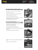
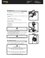
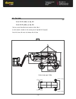
PURGING THE FUEL FILTER
- Loosen the purge screw 1 (Fig. G1/1)
- Operate the priming bulb 2 (Fig. G1/2) until the fuel flows air-free from the
purge scre
- Tighten the purge screw 1 (Fig. G1/1) while the fuel is still flowing.
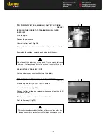
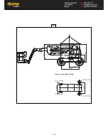
PURGING THE INJECTORS
- Loosen the hose connections 3 (Fig. G1/3) on one of the injectors.
- Press the starter until the diesel flows air-free from the hose connections 3
(Fig. G1/3).
- Tighten the hose connections while the fuel is still flowing
Do not engage the starter motor on a continual basis for more than 30
seconds and let it cool between unsuccessful attempts.
- The engine is now ready to be started.
- Turn the I.C. engine over slowly for 5 minutes immediately after bleeding the
fuel feed circuit, in order to ensure that the injection pump has been bled
thoroughly.
NOTE :
If the I.C. engine functions correctly for a short time then stops or
functions irregularly, check for possible leaks in the low pressure circuit. If in
doubt, contact your dealer.
3
3
3
3
2
G1/1
1
Summary of Contents for 160 ATJ
Page 2: ......
Page 4: ......
Page 6: ......
Page 7: ...1 1 1 OPERATING AND SAFETY INSTRUCTIONS 1 OPERATING AND SAFETY INSTRUCTIONS...
Page 8: ......
Page 25: ...1 19 REAR AXLE ASSEMBLY FIG E Axle type Serial Nr Maker s N E...
Page 28: ...1 22...
Page 29: ...2 1 2 DESCRIPTION 2 DESCRIPTION...
Page 30: ......
Page 31: ...2 3...
Page 37: ...2 9...
Page 39: ...2 11...
Page 41: ......
Page 74: ...2 46 MAIN DISTRIBUTOR Basket rotation Turret rotation Steering Pendular arm Tilt compensation...
Page 75: ...3 MAINTENANCE 3 MAINTENANCE...
Page 76: ......
Page 78: ......
Page 105: ...3 31...
Page 107: ...3 33 G3 2 Centre of gravity Platform s total weight 8090 Kg...
Page 111: ...4 ELECTRICITY 4 ELECTRICITY 4 1...
Page 112: ...4 2...
Page 114: ...4 4...
Page 115: ...5 1 5 OPTIONAL ACCESSORIES FOR THE RANGE 5 OPTIONAL ACCESSORIES FOR THE RANGE...
Page 116: ...5 2...
Page 120: ...5 6...
Page 121: ...6 1 6 MAINTENANCE HANDBOOK 6 MAINTENANCE HANDBOOK...
Page 122: ......
Page 130: ......
Page 131: ...Powered by TCPDF www tcpdf org...