background image

     54     

                    M&R Companies  440 Medinah Rd. Roselle, IL  60172 USA 


        Tel:  +630-858-6101      Fax:  +630-858-6134      

www.mrprint.com


| store.mrprint.com


V.120617


2. 

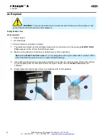
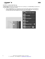
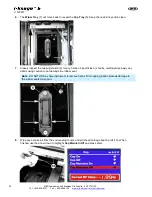
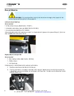
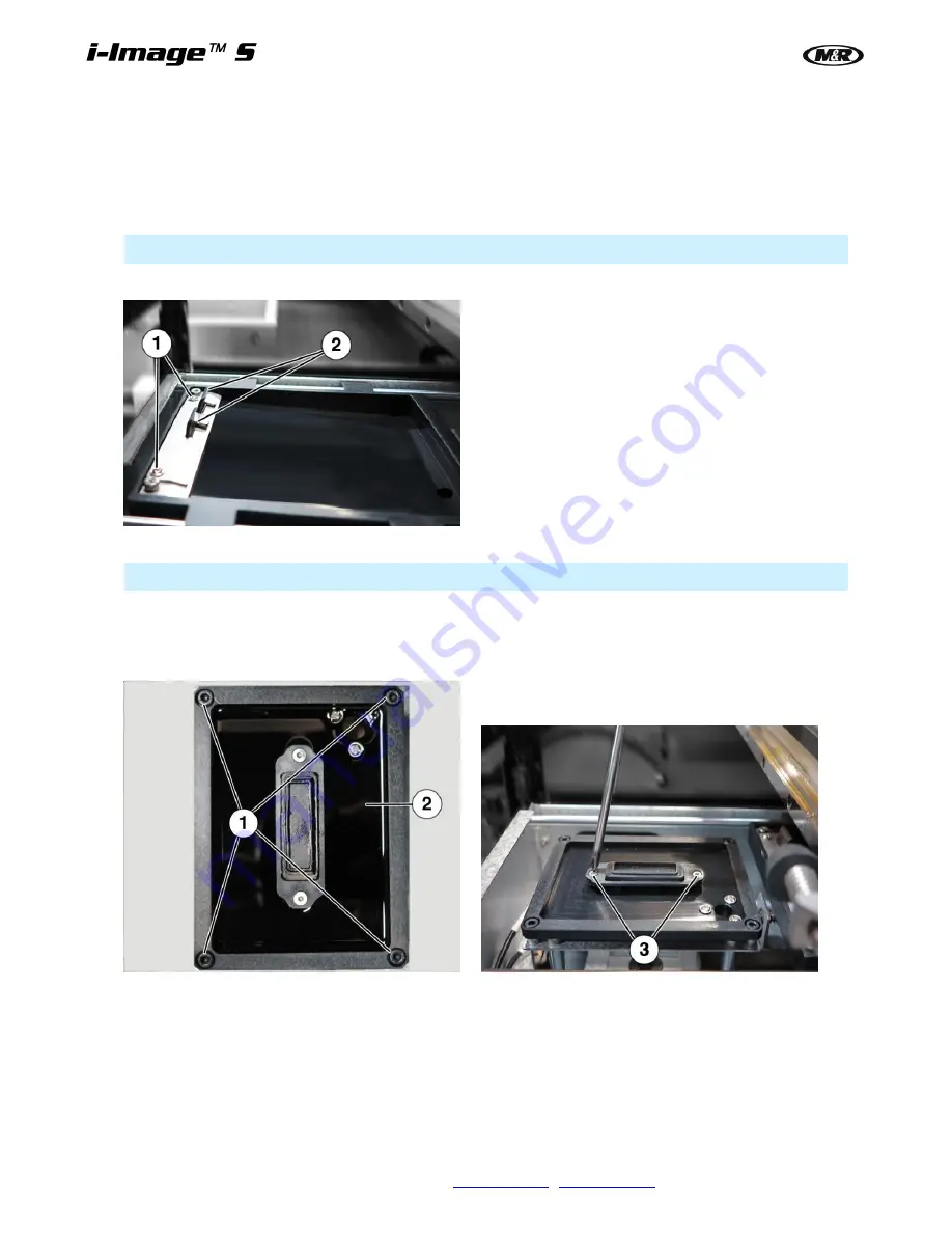
Using a Phillips screwdriver loosen the two bracket screws (1) holding the two wiper blades in place. 

3. 

Remove the individual wiper blades (2) by sliding each one out from the bracket. Thoroughly clean the 
parts in warm water and inspect for any damage, such as nicks, cuts or wear on the blade tips. Replace 
if damaged. While the blades are removed, wipe the entire tray to clean out any dried ink or heavy 
deposits. 

Note

:  It is recommended to replace the wiper blades every six months. 

4. 

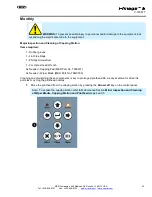
Replace the wiper blades in reverse order of disassembly. 


5. 

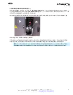
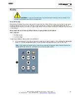
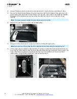
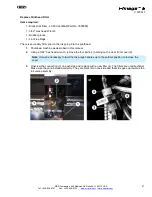
Using a 3 mm hex head wrench, remove the 4 bolts (1) holding the capping tray. 

Note

: Soak up some of the excess ink with an absorbent cloth before lifting the capping tray out. 

6. 

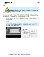
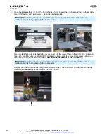
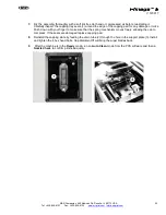
Lift the capping tray (2) straight up approximately 4" as there is a drain tube that extends down from the 
rear of the tray. After removal, clean the entire cap assembly by flushing it with warm running water. This 
helps to flush out any sediment and particles that may have accumulated under the spring loaded 
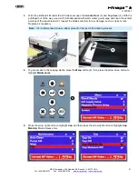
capping pads.  Using a Phillips screwdriver, remove capping pad (3). 


Summary of Contents for i-Image S

Page 1: ...i Image S Bv2 Part MAN i Image S V 120617...

Page 2: ......

Page 3: ...ter Control Panel 16 5 3 Tri Sync Bypass Switch 17 5 4 Startup 17 5 5 Shutdown 18 5 6 Printer Control Software PCS 20 5 6 1 Print Mode Settings 21 5 7 Print Preview Software PPS 22 5 7 1 Print preview...

Page 4: ...of the machine Energy Sources M R equipment may use one of more of the following energy sources Compressed Air Pneumatic Energy Electricity Gas Natural Gas or Propane Each form of energy presents its...

Page 5: ...the safe operation or normal functioning of this equipment ensure that the equipment is immediately shut down sources of power to the equipment are shut off and secured and that personnel not trained...

Page 6: ...orking on or near this equipment are knowledgeable in its safe operation and closely supervise inexperienced employees keep bystanders away from the equipment 6 Make sure the area around the equipment...

Page 7: ...ation of notice to holders of this document with respect to changes subsequently made M R Printing Equipment Inc and its subsidiaries make no representation or warranty expressed or implied whether pu...

Page 8: ...cord the information from your product s rating plate on the sample plate shown below Date Installed Installed by Optional Features and Special Information Contacting M R If you need service or have q...

Page 9: ...rigid flat substrates as more fully set forth in the manual specific to that product Any other use of this equipment is not permitted Exposure Equipment Exposure Equipment is designed to produce photo...

Page 10: ...proper installation or use of the equipment 3 Operation of the equipment with defective safety devices 4 Operation of the equipment with safety devices removed disabled not working in whole or in part...

Page 11: ...ize H x W x D 127 x 152 x 168 cm 50 x 60 x 66 Screens per Shift 5 100 Shipping Weight 363 kg 800 lb 1 If incoming voltage differs from the voltage s listed in this brochure calculate amperage accordin...

Page 12: ...om the machine operates in should be relatively comfortable with the temperature not exceeding 85F 4 1 2 Power Requirements It is Very Important that the unit be connected to a dedicated electrical se...

Page 13: ...edinah Rd Roselle IL 60172 USA 13 Tel 630 858 6101 Fax 630 858 6134 www mrprint com store mrprint com V 120617 4 1 4 Power Box Plug cord 2 from Power Box 1 into On Off Switch 3 Power Box 1 main power...

Page 14: ...at draw ink from the main tank located in the base of the machine filling a small sub tank located inside the Printhead assembly The sub tank has a positive and negative air regulating system that bal...

Page 15: ...and system status messages 2 Print Counter Display Used to count the total number of prints 3 Print Button Blue button used to start printing process 4 Power On Button Green button turns the power ON...

Page 16: ...3 Arrow Keys Used to select settings or change parameters 4 Power Light Illuminates when the power is On 5 Enter Button Used to confirm or enter menu selection The four arrows move the printhead and...

Page 17: ...e installation and startup Note Only personnel trained on the machine should operate the i Image S IMPORTANT Before printing always do a nozzle check See Printing Nozzle Checks in the Daily Scheduled...

Page 18: ...e vertical closed position Rotate valve levers up until they make contact to the metal stop plate Note Follow this procedure for Long term shutdown only 2 Press and hold Abort button 2 for 3 4 seconds...

Page 19: ...el 630 858 6101 Fax 630 858 6134 www mrprint com store mrprint com V 120617 4 If shutting the machine down for an extended period of time turn OFF the Main Power 5 and Power Box Disconnect Switch 6 on...

Page 20: ...sed It can also be overridden by the ripped file settings Printer Setting 2 Indicates Number of Passes Speed and print modes This is described in detail in the Print Mode Settings section of this manu...

Page 21: ...pass For most work high speed is the preferred setting For fine halftone printing 55 to 65 Lpi and higher printing in the low speed setting is recommended The i Image S is low speed only Number of Pa...

Page 22: ...ains these commonly used functions Open adds one or more prt files to the software Parse continues the parsing process loads the job and generate preview for every channel if the loading process was c...

Page 23: ...art department PPS allows the operator to confirm crucial job information and select which plates to process The prt files can be imported by either clicking on the File Open icon 1 or by clicking on...

Page 24: ...nd deleted from the print queue Note The ColorPRINT RIP can be configured to send files automatically to the Hot folder From there the PPS software will automatically import and open it ColorPRINT has...

Page 25: ...t mesh counts 5 7 5 Display Modes Single and Multi View Files can be displayed in two Modes Single channel 1 displays the selected channel as a black and white image in the bottom preview pane For scr...

Page 26: ...background with the image as white Note The Black background setting does not work in Multiple File Display Mode Zoom Function The Zoom Function allows operators to inspect details of a selected imag...

Page 27: ...store mrprint com V 120617 The Zoom function works with the Single file on the Black background This is helpful when confirming white underbase plates The Zoom function also works in the Multiple Chan...

Page 28: ...int button 2 To print all the color plates in a certain job click on the top color plate and hold down the Shift key on the keyboard Then click on the bottom color plate 4 to select all the plates for...

Page 29: ...the art board in relation to the image top and the art board top is important as well as centering the image right to left on the art board Specialized placements such as left chest pocket print and s...

Page 30: ...the RIP Layout Tab settings This sets the image at 6 inches from the O D of the frame All measurements and settings can be modified to meet the end users needs but ultimately standardizing art board...

Page 31: ...858 6101 Fax 630 858 6134 www mrprint com store mrprint com V 120617 A typical art board template will have a center line an i Image top position start line and designations for right and left chest...

Page 32: ...with multiple color channels in Photoshop 2 To save the image as a DCS 2 0 file use the Save As menu and select the Format DCS 2 0 EPS 1 Check Spot Colors option 2 3 Click the Save button and the DCS...

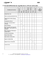
Page 33: ...tware also has an option to automatically print color plate information as well as registration marks on each screen 1 When Creating art or finalizing supplied art to be ripped using ColorPRINT Spot C...

Page 34: ...ion and or registration marks Refer to Art preparation and Image Placement in this manual 6 2 1 Exporting Files from Illustrator Export finished art from Illustrator as an Illustrator EPS file 1 Use S...

Page 35: ...oose Add Setup 1 displays On the screens shots you will notice the multiple printer setups that have been made on this particular ColorPRINT RIP install Each one has specific settings and parameters t...

Page 36: ...is box unselected Since the RIP is processing art for direct printing on the screens bottom surface the Mirror option 3 should be selected Unless you are making screens to print transfers Selecting RI...

Page 37: ...ng Changing resolutions may also require the i Image S operator to select a corresponding Print Mode in the PCS software Refer to Print Mode Settings in this manual Dithering Use Angled Screen 2 when...

Page 38: ...t works best for your printing scenarios and shop conditions Curves Select the Curves 1 option and either click on the intersecting graph line where you want to adjust the curve and drag it to the req...

Page 39: ...the PCS Print Modes However in most cases the system will be configured to print to File which voids the Print Mode selection leaving that function to the I Image S operator Over Print The Over Print...

Page 40: ...t window allows you to Browse to the connected network and designate a folder to Print To Note The designated folder should be somewhere on the network main frame With a single Print To setup if a hot...

Page 41: ...n be automated so that any prt files that are sent to a designated Hot Folder are automatically opened in the PPS printer queue if the Enable Hot Folder 1 is selected When deleting job automatically d...

Page 42: ...ired network folder and either double click on the required file or highlight it and click on Open 3 3 If the RIP is set up to RIP and print jobs automatically each of the individual Printer Setups sh...

Page 43: ...managed preventive maintenance program can minimize downtime Preparation An effective preventive maintenance program includes proper selection handling and application of lubricants stocking high qual...

Page 44: ...ead cleaning When the tank is full the message WASTE TANK FULL appears on the Printer Control Panel screen 2 Make sure the printer is not printing or performing any other operations Note Attach Waste...

Page 45: ...is automatically eliminated Remove cap and fill the left ink tank 1 with ink or the right cleaning tank 2 with cleaning fluid Replace caps Clean Operator Interface Display Screen If the screen surface...

Page 46: ...ring at 100 On the right hand side of the Main PCS window is the maintenance header bar which is used for Nozzle Checks 1 Start by loading a screen into the machine Then lightly spray tack a piece of...

Page 47: ...ess the Print button 3 on the control panel or Print Screen The gantry travels to the print start position prints one nozzle check and automatically sends the gantry to the load position 5 Inspect the...

Page 48: ...d and portions were found not printing 1 run an Auto Clean It may take two or three Auto Cleans to purge large air pockets 1 Select the Auto Clean box 2 in the right hand menu bar of the PCS Program T...

Page 49: ...REUSE waste ink If maintenance tank has any sediment or sludge in the bottom rinse and clean it with water Refer to Clean Ink Tank in this manual Minor Inspection and Cleaning of Wiper Blades Capping...

Page 50: ...into the nozzle ports Use a work light to illuminate inside the covers to get a better view of the printhead 1 With a clean lint free cloth carefully wipe the bottom of the printhead carriage plate t...

Page 51: ...ater gently wipe and clean the vertical portions of the wiper blades 5 Inspect the blades carefully for any damage such as nicks or cuts Replace as necessary Note It is recommended to wear rubber glov...

Page 52: ...inspect the capping station 9 for any harden ink particles or chunks carefully wipe away any debris using caution to not damage the rubber seal Note DO NOT USE a sharp instrument to remove debris fro...

Page 53: ...ves 1 Lint Free Rags 1 Phillips Screwdriver 1 3 mm Hex Head Wrench As Needed Capping Pad M R Part No 7990127 As Needed Wiper Blade M R Part No 7AM0030 Cleaning and maintaining these components is key...

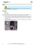
Page 54: ...t any dried ink or heavy deposits Note It is recommended to replace the wiper blades every six months 4 Replace the wiper blades in reverse order of disassembly 5 Using a 3 mm hex head wrench remove t...

Page 55: ...ad for any damage or nicks Push down with your finger to make sure that the spring mechanism moves freely allowing the cap to compress If the seals are damaged replace capping pad 8 Reinstall the capp...

Page 56: ...sion M R Part No 3030051 Using a standard pump action grease gun apply 1 or 2 applications of grease to the grease fittings 1 front and rear on both sides of the screen frame Replace Main Ink Pump Fil...

Page 57: ...or to the ink going into the printhead 1 Shutdown machine as described in this manual 2 Using a 3 32 hex head wrench remove the four bolts 1 holding on the clear front cover 2 Note It may be necessary...

Page 58: ...about the one year mark watch the ink level The best time to clean the tank is when it drops low enough to display a low ink level message 1 Open door and remove the tank 1 and pour out any remaining...

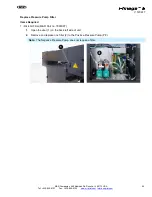
Page 59: ...rprint com store mrprint com V 120617 Replace Pressure Pump Filter Items Required 1 Disk Air Filter M R Part no 7990007 1 Open the door 1 on the back left side of unit 2 Remove and replace one filter...

Page 60: ...s Date performed Initials Empty Waste Tank x Fill Ink and Cleaning Solution Tanks x Clean Operator Interface Display Screen x Printing Nozzle Checks x Auto Clean Automated Head Cleanings x General Cle...

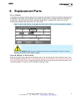
Page 61: ...late similar to the one shown below Note You must verify whether your equipment is 50 Hz CE or 60 Hz UL and order parts accordingly DANGER Operating this equipment with incorrect electrical parts can...

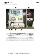
Page 62: ...int com V 120617 Boards Power Supplies and Filters UL CE Boards Power Supplies and Filters UL CE Part Name Part Numbers All Models 1 Main Board V4 7 7990152 2 Black Needle Filter 7990002 3 X Motion Dr...

Reviews: