36
solutions creator
ITALIANO
ENGLISH
UTILIZZO PROGRAMMA EASY ALUDATA
Selezione programma di equilibratura
Dalla PAGINA PRINCIPALE entrare nella “Selezione tipo ruota”.
I programmi ALUDATA sono:
3. ALU 2
4. ALU 3
9. Pax 2
Selezionare il programma di equilibratura in modalità ALUDATA.
Impostazione dati ruota
• Estraendo il calibro di misurazione interna dalla sua posizione di riposo si passa automaticamente alla “Misure
ruota”.
• Posizionare il calibro nella prima posizione prescelta per l’equilibratura, rimanere fermi e attendere il “beep” di
conferma.
• Successivamente posizionare il calibro nella seconda posizione prescelta per l’equilibratura, rimanere fermi e atten-
dere il “beep” di conferma.
• Al termine riportando il calibro nella posizione di riposo si torna automaticamente pagina principale.
Equilibratura ruote
A. Dopo aver chiuso il carter di protezione della ruota inizia il ciclo di misura.
B. Determinati i dati della misura, la ruota viene frenata automaticamente fino all’arresto.
C. La grandezza e posizione degli squilibri dei due lati della ruota vengono determinati in un unico lancio di misura, e
sono indicati separatamente sui visualizzatori.
D. Le frecce indicano la direzione in cui deve essere girata la ruota per il posizionamento nel corretto punto di equili-
bratura (indicazione separata per ciascun lato della ruota).
E. Girare a mano la ruota finché la freccia di sinistra (corrispondente al fianco interno) si colora completamente di
rosso (sia nella parte superiore sia nella parte inferiore; il segnale acustico, se abilitato, indica il raggiungimento
della posizione corretta.
F. Inserire il peso adesivo del valore richiesto per l’equilibratura nella apposita sede sul tastatore di misura con la
parte adesiva rivolta verso l’alto, avendo rimosso la pellicola protettiva; estrarre il tastatore stesso verso la posizione
di equilibratura; il raggiungimento della posizione esatta viene confermato da un “beep” acustico se abilitato; ruotare
il calibro per avvicinare il tastatore al cerchio ed applicare il peso.
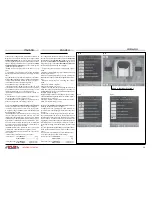
In questa fase sul monitor compare un’icona che visualizza la posizione attuale del tastatore di misura rispetto ai
piani di equilibratura prescelti; il raggiungimento della corretta posizione di equilibratura, corrisponde alla condizione
in cui:
- la ruota è nella corretta posizione angolare per l’equilibratura;
- il tastatore è posizionato sul piano di equilibratura corrispondente;
- il tutto viene visualizzato sul monitor.
G. Ripetere le operazioni E ed F per l’altro fianco.
Nota: nel programma SEPARAZIONE PESI le operazioni E ed F devono essere ripetute per entrambi i pesi da applicare
sul fianco esterno nelle esatte posizioni dietro alle razze (come visualizzate sul monitor).
USING THE EASY ALUDATA PROGRAM
Selecting balancing program
From MAIN PAGE enter “Wheel type selection”.
The ALUDATA programs are:
3. ALU 2
4. ALU 3
9. Pax 2
Select the ALUDATA mode balancing program.
When the most suitable balancing program has been selected, press the OK or STOP button to return to the main
page.
Setting wheel data
• When the inside gauge is extracted from its idle position the LED for the selected position starts flashing on the
control panel.
• Locate the gauge at the first position selected for balancing, remain still and wait for the confirmation “beep”.
• Now locate the gauge at the second position selected for balancing, remain still and wait for the confirmation “beep”.
The LED corresponding to the chosen position will flash on the control panel.
• Finally, moving the gauge back to the neutral position returns automatically to the main page.
Wheel balancing
A. Close the guard cover and begin a measuring cycle.
B. When the readings have been established the wheel is automatically braked until it stops.
C. The scale and position of imbalance on the two sides of the wheel are established in a single measuring cycle and
are shown separately on the displays.
D. The arrows indicate the direction the wheel must be turned for the positioning at the point of imbalance (separate
indications for the two sides of the wheel).
E. Turn the wheel by hand until the left arrow (corresponding to the inner side) gets fully red (both in the upper and in
the lower part); the sound signal, if enabled, indicates when the correct position is reached.
F. Insert the required adhesive weight for balancing into the seat in the measuring feeler with the adhesive part facing
up, after removing the protective film. Extract the feeler towards the imbalance position and wait for the confirmation
“beep”, if enabled. Now rotate the gauge to bring the feeler into contact with the rim and apply the weight. During this
stage, an icon will be displayed showing the position of the probe in relation to the selected balancing planes. When
the correct balancing position is reached the displays show a symbol corresponding to the conditions:
- The wheel is in the correct angular position for balancing.
- The probe is positioned on the corresponding balancing plane.
- All the operation will be showed on the video.
G. Repeat operations E and F for the opposite side.
Note: in the WEIGHT SEPARATION program, the E and F operations must be repeated for both weights to be fitted on
the outside in the correct positions behind the spokes. (as shown on the display).


