background image

34

solutions creator

ITALIANO

ENGLISH

  TARATURA BASE DELLA MACCHINA

Sono neccessari due metodi di prova per assicurarsi che l’equilibratura avvenga in modo perfetto.

PROVA DI BUON FUNZIONAMENTO DELLA BILANCIATURA

• Si equilibrano sulla macchina i due lati della ruota, seguendo le istruzioni.

• Quindi si produce artificialmente uno squilibrio, applicando un peso di 50 grammi su uno dei due lati. La macchina 

deve indicare esattamente questo squilibrio, sia l’entità che la posizione, mentre può esservi un’indicazione massima 

di 5 grammi per l’altro lato.

• Per controllare la posizione dello squilibrio si gira la ruota sulla posizione di squilibrio indicata dalla macchina tramite 

l’indicazione delle frecce sul monitor (ore 6). In tale posizione, il peso di prova applicato deve trovarsi verticalmente 

sotto l’asse di rotazione (ore 6).

• Se vi sono delle deviazioni angolari chiaramente visibili, occorre rettificare l’indicazione.

• Se si verificano deviazioni inaccettabili sull’entità di squilibrio indicato, per il lato della ruota dove è applicato il peso 

di prova, oppure c’è un’indicazione eccessiva sull’altro lato della ruota, bisogna ritarare la macchina.

PRECISIONE DI CENTRATURA (Qualità di Equilibratura)

• A tal scopo si può impiegare la ruota già equilibrata nella prova precedente. Togliere il peso di prova. Quindi sbloccare 

la ruota dall’attrezzo adattatore e ribloccarla, ma spostata di circa 35°.

• In un lancio di prova, l’indicazione non deve superare un massimo  squilibrio di 5 grammi su ogni lato (10 g. in caso 

di ruote particolarmente pesanti). Questo errore è dovuto alle tolleranze nella centratura del cerchio.

• Una centratura precisa è essenziale sia per questa prova che nella normale procedura di equilibratura. Se in questo 

lancio di prova si rileva uno squilibrio elevato, bisogna controllare l’usura,  i giochi e la sporcizia delle parti impiegate 

per centrare la ruota.

 AUTODIAGNOSI

È prevista una PAGINA di AUTODIAGNOSI per verificare il corretto funzionamento della macchina equilibratrice: dalla 

PAGINA PRINCIPALE premere il tasto MENÙ di SERVIZIO; da qui, premere il tasto AUTODIAGNOSI EQUILIBRATRICE; in 

questa pagina il monitor visualizza i seguenti valori:

• tensione di alimentazione e tensione di riferimento;

• tensioni dei calibri distanza, larghezza, diametro;

• tensione e fase del pick-up interno (rilevato durante l’ultima misura);

• tensione e fase del pick-up esterno (rilevato durante l’ultima misura);

• differenza di fase (calcolato);

• posizione angolare (in impulsi encoder: da 0 a 399) dell’albero;

• velocità (in giri al minuto) dell’albero: premendo il tasto START è possibile verificare la velocità di regime della 

macchina.

• tensione di uscita dal sensore di rotondità.

• tensione di alimentazione del sensore di rotondità.

• tensione pick-up interno (in tempo reale).

• tensione pick-up esterno (in tempo reale).

  BASIC MACHINE CALIBRATION

Two test procedures are necessary to ensure that wheel balancing is conducted accurately.

BALANCING ACCURACY TEST

• Balance the two sides of a wheel according to the instructions.

• Artificially create an imbalance by fitting a weight of 50 grams on one side of the wheel. The machine should iden-

tify this imbalance precisely, both for weight and position. A reading up to a maximum of 5g is possible for the other 

side.

• In order to check the position of the imbalance, turn the wheel to the balancing position as indicated by the arrows 

on the monitor (6 o’clock). In this position the test weight should be vertically below the rotation axle (6 o’clock).

• If there is an obvious angular error the indicators have to be rectified.

• If there is an unacceptably big weight error on the side with the test weight, or an excessive figure for the opposite 

side of the wheel, the machine has to be recalibrated.

CENTRING PRECISION (Balancing Quality)

• The wheel balanced in the previous test can be used. Remove the test weight. Release the wheel from the adapter 

and retighten it, but rotated by about 35°.

• In a test cycle the imbalance must not exceed a maximum of 5 g on each side (10 g in the case of particularly heavy 

wheels). This error is due to the rim centring tolerance.

• Precise centring is essential both for this test and during normal balancing operations. If this test run produces a high 

imbalance reading check the parts used for centring the wheel for wear, play, and dirt.

 SELF-DIAGNOSIS

A SELF-DIAGNOSIS PAGE is provided to check the correct operation of the balancing machine. From the MAIN PAGE press 

the SERVICE MENU key. From here, press the WHEEL BALANCER SELF-DIAGNOSIS key; in this page the monitor displays 

the following vaues:

• Supply voltage and reference voltage.

• Voltages for the distance, width, and diameter gauges.

• Voltage and phase of the internal pick up (read during the last measurement).

• Voltage and phase of the external pick up (read during the last measurement).

• Phase difference (calculated).

• Angular position (in encoder impulses: from 0 to 399) of the shaft.

• Speed (in rpm) of the shaft: by pressing START the machine’s operating speed can be checked.

• Output voltage from the roundness sensor.

• Roundness sensor supply voltage.

• Internal pick-up voltage (in real time).

• External pick-up voltage (in real time).

Summary of Contents for WB 690

Page 1: ...E AUSWUCHTMASCHINE EQUILIBRADORA solutions creator WB 690 cod 300346 rev 05 MANUALE D ISTRUZIONE ORIGINALE ORIGINAL INSTRUCTIONS MANUAL MANUEL D INSTRUCTIONS ORIGINAL ORIGINALE ANLEITUNGSHINWEISE MANUAL DE INSTRUCCIONES ORIGINAL ES DE FR UK IT ...

Page 2: ......

Page 3: ...hat of the equipment should be used Cords rated for less current than the equipment may overheat Care should be taken to arrange the cord so that it will not be tripped over or pulled 5 Always unplug equipment from electrical outlet when not in use Never use the cord to pull the plug from the outlet Grasp plug and pull to disconnect 6 Save these instructions INSTRUCTIONS IMPORTANTES DE SÉCURITÉ NE...

Page 4: ... ed irragionevoli Per l utilizzo della macchina è previsto un solo operatore che ha l obbligo di mantenere le persone esposte lontano dall area di pericolo durante tutte le fasi di lavoro 3 metri intorno alla macchina Questo simbolo viene utilizzato nel presente manuale quando si vuole attirare l attenzione dell operatore su particolari rischi connessi con l uso della macchina L operatore ne è il ...

Page 5: ... risques de la machine Le non respect des instructions peut provoquer des dégâts à la personne qui en certains cas pourraient être tellement graves à en entrainer la mort Lamachineestpourvue desonpropresystèmed allumage Exécutertoutesles opérations de travail dans des pièces pourvues d un bon éclairage Pour toute opérationdedéballage installation emploiouentretienseservirdeDispositifs de Protectio...

Page 6: ...mette l introduzione di ruote aventi un dia metro esterno massimo di 1120 mm 44 Dispositivi di sicurezza standard tasto STOP per l arresto delmotoreincondizionidiemergenza carterdiprotezio ne ruota quando il carter è aperto un dispositivo elettri co impedisce l avviamento della macchina ILLUSTRATIVE MACHINE DRAWING indicating the main parts relevant to use KEY A MAIN SWITCH B POWER SUPPLY CABLE C ...

Page 7: ...derMasseinmmermöglicheneineeinfacheundschnelleAnwendung der Maschine Dynamische Standardauswuchtprogramme 5 ALU Programme 3 statische Programme für Motorrad oder Kraftfahrzeugräder mit der Anbringung von haftendenoderfederndenGegengewichten zweispezielleALU Programme fürPAX Räder MöglichkeitderGewichtetrennung statischesAuswucht opti mierungsprogramm Selbstdiagnose undSelbsteichungsfunktionen died...

Page 8: ...ghezza 1035 mm PESO Peso Netto con carter 76 kg Peso Lordo 105 mm MOTORE ELETTRICO Alimentazione 3 modelli 115V 1 60Hz 230V 1 50Hz 230V 1 60Hz Potenza 350 W Fasi 1 Protezione IP 22 Velocità di equilibratura 167 giri min a 50Hz 200 giri min a 60Hz Risoluzione lettura squilibrio 1 5 g 0 01 0 25 oz 1 4 Rumorosità 75 db GAMMA DI APPLICAZIONI SBM 55 55s è progettata per equilibrare ruote d autovettura ...

Page 9: ...äder MotorradräderundLKW Räderentworfenundgebautwurde Die Arbeitskapazität der Maschine ist folgende min max Radabstand 50 315 mm Felgenbreite 2 16 Max Radbreite mit min 50mm Abstand 500mm Felgendurchmesser 8 30 Raddurchmesser 1120 mm 44 Radgewicht 70 kg Max Gewicht Motorradräder 20 kg Max Gewicht KFZ Räder 70 kg Max Gewicht LKW Räder 200 kg Anm Die o a Mindest und Höchstmasse beziehen sich auf di...

Page 10: ...i precise e costanti ACCESSORIES ON REQUEST fig 4 KEY 1 3 4 5 Hole adapter with standard nuts 2 Quick release nuts 3 Motorcycle wheel adapter 4 Spacer 5 Centring rings for Renault Citroën Peugeot UNPACKING After removing the packing strapping seals cardboard and the pallet see fig 5 check the machine for missing or damaged parts If in doubt do not use the machine and refer to professionally qualif...

Page 11: ...andardzubehör befindet sich in der Maschinenver packung AUFSTELLUNG Die Auswuchtmaschine muss auf einen soliden Boden aus Zement oder ähnlichemMaterialgestelltwerden EinesichdarunterbefindendeLeerekann zu Ungenauigkeiten bei der Auswuchtsmessung führen RAUMBEDARFSABMESSUNGEN 2230 mm x 1350 mm x 1310 mm SICHERHEITSABSTÄNDE Für eine sichere und ergonomische Anwendung der Maschine empfiehlt es sich d...

Page 12: ... della macchina Se la rotazione avviene nel senso sbagliato la macchina si arresterà immediatamente Nel caso in cui si verificasse un uso anomalo della mac china azionareimmediatamentel interruttoregenerale A in fig 8 e controllare il manuale di istruzioni nella se zione malfunzionamenti E vietato togliere tensione alla macchina mediante il distacco della spina dalla presa di corrente o dalla macc...

Page 13: ...Teiler mit einer Öffnung der Kontakte von min destens3mm entsprechendderEuropäischenVorschriften DieSicherheitssi cherungenderSteckdosemüssen3Afür230VACMaschinenund6Afür115VAC Maschinen lauten Den Verbinder des Breitekalibers verbinden D Abb 8 Ist der Anschluss erfolgt die Maschine mittels Hauptschalter einschalten A Abb 8 BETRIEBSÜBERPRÜFUNGEN Abb 9 Drückt man den START Knopf mit gesenkter Schutz...

Page 14: ...balancing operation The illustrations show the flange fastening system fig 11 shows the cone flange fixing system fig 12 shows the 3 4 5 hole universal flange fixing sy stem fig 13 shows the motorcycle flange fixing system WHEEL LOCKING AUTOMOBILE WHEEL LOCKING figures 14 and 15 show the automobile wheel locking system using the cone flange fig 16showstheautomobilewheellockingsystemusing the 3 4 5...

Page 15: ...INSTALACIÓN BRIDAS MONTAJE BRIDAS Antes de fijar las bridas a la máquina es oportuno limpiar el cono del árbol de lamáquinayelagujerodelabrida Unamalaadaptacióndelabridainfluiráen la precisión del equilibrado Las ilustraciones muestran el sistema de fijación de las bridas La fig 11 muestra el sistema de fijación de la brida de conos La fig 12 muestra el sistema de fijación de la brida universal 3 ...

Page 16: ...asto OK per entrare nel menù scelto N B Quando la macchina lavora in modalità autocarro nel riquadro in alto a sinistra comparirà l immagine di fig 18 1 fig 18 fig 18 1 3 ITALIANO ENGLISH 4 5 6 9 8 7 10 INSTRUCTIONS FOR USE CONTROL PANEL KEY 1 High definition colour monitor 2 Functions back keys 3 STOP stop key 4 START start up key 5 OK data confirmation key 6 Data programming keys 7 Imbalance fig...

Page 17: ...EIGER RADDATEN 10 ANZEIGER FÜR FUNKTIONSTASTEN Anm Erfolgt die Drehung nicht mittels Elektromotor wird bei Drücken des Bremspedals die Raddrehung blockiert DieFunktionenderMaschinesindinverschiedenenSeitenzusammengefasst der Zugang zu den verschiedenen Seiten erfolgt mittels einer Menüstruktur Steuertafel Directionstasten für die Auswahl der Menüs OK Taste zum Ein tritt in das ausgewälte Menü N B ...

Page 18: ...a Quindi si applica il peso di equilibratura richiesto nei lati rispettivi della ruota in posizione perpendicolare in alto ore 12 sull albero principale Messi i contrappesi nelle posizioni corrette riavviare la macchina per verificare l esatta equilibratura ruota WHEEL BALANCING Witch on the machine with the main switch fig 8 When the machine switches on the MAIN PAGE fig 18a On fig 18d it is poss...

Page 19: ...nnen Nach Bestimmung der Messdaten wird das Rad automatisch bis zumHalt gebremst DerRadschutzdarfnichtvorhergeöffnetwerden DieHaltetasteSTOPhatdie Funktion die Maschine im Notfall zu blockieren DieUnwuchtsgrösseund positionderbeidenRadseitenwirdmiteinemein zigen Messtart bestimmt und wird auf den Anzeigern separat angegeben Die Pfeile geben die Richtung an in der das Rad gedreht werden muss an der...

Page 20: ...ei con trappesisulcerchioinbasealprogrammadiequilibratura prescelto All accensionelamacchinasiconfiguraautoma ticamente in programma dinamica standard Tornare alla PAGINA PRINCIPALE tramite il tasto uscita SELECTING BALANCING PROGRAM The use of various types of counterweights for balancing the various types of rims steel or light alloy produces differences between nominal measurements set for the ...

Page 21: ...ischenKFZ Räder Motorradräder LKW Räder wählen BeiDrückenderTasteOKleuchtetnachallenfolgendenverfügbarenAuswucht programmen dynamische Standardauswuchtung mit Spange angebrachte Gewichte 5 Alu Programme zur Auswuchtung für die dynamische Auswuchtung mit Haftgewichten 3 statische Auswuchtprogramme Haft oder mit Spange angebrachte Gewichte 2 spezielle Alu Programme zur Auswuchtung der Reifen PAX Mic...

Page 22: ...rammi molletta adesivi ta o adesivi ci PAX Michelin pesi sul cerchio in programma fig 20 contro ma ngono inseriti senza alcuna per i programmi ogrammazione dispositivo o 6 in fig 19 19 della ruota e riportata sul ro in dotazione erchio stesso del cerchio con e dalla scala e di motociclo casi si utilizza valore corretto nza e larghezza chio è pollici re il tasto MM no sulla ruota a in mm er larghez...

Page 23: ...Taste Raddaten eingeben drücken Auf der Vordertafel die Werte der Breite Durchmesser und Entfernung des Rads mit dem man arbeitet muss folgendes vorgegeben werden Der Messwert bezüglich der Felgenbreite ist im allgemeinen auf der Felge angegeben oder man misst mit dem mit der Maschine geliefertem Kaliber Abb 20a Der Felgendurchmesser ist im allgemeinen auf der Felge selbst angegeben oder kann auf ...

Page 24: ... modo seguente premere il tasto SPLIT per entrare nel programma di separazione dei pesi il display di sinistra visualizza n ed il display di destra visualizza il numero di razze attualmente impostato impostare se necessario il numero di razze desiderato da 3 a 12 utilzzando i tasti 5 fig 19 il display di destra mostra il valore modificato successivamente occorre muovere la ruota per portare una ra...

Page 25: ...nSpeichen aufgeteilt werden Aus der HAUPTSEITE die Taste Gewichtetrennung drücken um in das Programm einzugehen das Display zeigt das Bildschirm von Abb fig 23 die Anzahl der gewünschten Speichen eingeben anschließend ist das Rad zu bewegen um eine Speiche in die Stellung 12 Uhr zu bringen Abb 22 und während man das Rad in dieser Position Beibehält auf die OK Taste drücken dasProgrammzeigtdieSeite...

Page 26: ...rretta conclusione della procedura di ottimizzazione Fase 8 nel caso in cui la prima riduzione non sia stata soddisfacente la macchina propone automaticamente di pro seguire nell operazione di riduzione ripetendo le operazioni descritte a partire dalla fase 5 Quando non è più possibile ridurre ulteriormente lo squilibrio la procedura termina OPTIMISING IMBALANCE This program allows the reduction o...

Page 27: ... vorhergehendenVorgänge mit höchster Genauigkeitvorgenommenwerden BeiEndedeszweitenStartszeigtderMo nitor folgende Werte an Wert der statischen Unwucht der Felge Wert der statischen Unwucht des Reifens Wert der aktuellen statischen Unwucht des Rads Wert der minimalen empfohlenen bleibenden Unwucht den man erzielen kann Durch Untersuchung dieserWerte entscheidet man ob es vorteilhaft ist mit dem Un...

Page 28: ...sonalizza nomi utenti procedere come per intesta zione cliente Seleziona impostazioni europee o americane valori europei TOLLERANZA 4 5 g RISOLUZIONE 5 g valori americani TOLLERANZA 7 g 0 25 once RISOLUZIONE 5 g 0 18 once CONFIGURING THE WHEEL BALANCER The configuration functions allow users to set the machi ne to their particular requirements From the MAIN PAGE pressing the key of SERVICE MENU fi...

Page 29: ...veranschaulichungsschritt aktiviertmandasMenümitdenOptio nen 1 VeranschaulichungdesUnwuchtswertsmitFeinauflösung d h Schrittevon 1 Gramm 0 035 Once 2 VeranschaulichungdesUnwuchtswertsmitStandardauflösung d h Schritte von 5 Gramm 0 18 Once GehtmanzurZWEITENSEITEderPERSÖNLICHENGESTALTUNGüber inderman folgende Parameter vorgeben kann fig 27 Sprache aktiviert man das Fenster in dem man die Sprache wäh...

Page 30: ...libration temporary wheel balancing CALIBRAZIONE EQUILIBRATRICE Dalla PAGINA PRINCIPALE premere il tasto Seleziona menu di servizio fig 28 da qui premere il tasto Menu calibrazione equilibratrice fig 29 si attiva la finestra di richiesta del codice di accesso alle funzioni riservate per procedere occorre digitare correttamente il codice di accesso 3 5 fig 30 e premere il tasto UP fig 31 nell Actio...

Page 31: ...des Zugangskode zu den geheimen Funktionen umfortzufahrenmussderZugangskode 3 5 Abb 30 korrektangegebenwer den und die UP Taste Abb 31 an der Action Center gedrückt werden auf dieseWeisegehtdasProgrammindasKALIBRIERUNGSMENUein dassichaus folgenden Funktionen zusammensetzt Abb 32 Unwuchskorrektur Flansch Eichung der automatischen Kaliber Selbsteichung Auswuchtmaschine momentane Auswuchtung eines Ra...

Page 32: ...appositaflangiafissatabene impostareidati dellaruotaconicalibriautomaticiomanualmente assicurarsicheilprogrammasia inautocarro vedifigurainaltoasinistrasulmonitor esiripetetutteleoperazioni 3 4 5 6 7 8comesullavettura CALIBRATING THE AUTOMATIC GAUGES From balancercalibrationmenu pressthe automaticgaugescalibration key fig 32 For the calibration of the gauges it is necessary to operate withoutwheel...

Page 33: ...öglichtes elektronisch eventuellbleibendeUnwuchtinZusammenhangmitderWelleoderdemZentrierungsflanschauszu gleichen ZweiteEichphase sieheKap Eichung automatischeKaliber DritteEichphase SelbsteichungAuswuchtmaschine 1 EinKraftfahrzeugradingutemZustandmitmittlerenAbmessungen Durchmesser14 aufdem Kegelflanschanbringenundgutbefestigen AlleamRadeventuellvorhandenenBleigewichteab nehmen 2 MitgrosserSorgfa...

Page 34: ...in impulsi encoder da 0 a 399 dell albero velocità in giri al minuto dell albero premendo il tasto START è possibile verificare la velocità di regime della macchina tensione di uscita dal sensore di rotondità tensione di alimentazione del sensore di rotondità tensione pick up interno in tempo reale tensione pick up esterno in tempo reale BASIC MACHINE CALIBRATION Two test procedures are necessary ...

Page 35: ...tung lösen und erneut blockieren jedoch um ca 35 verschoben Bei einem Probestart darf die Anzeige eine Höchstunwucht von 10 Gramm auf jeder Seite 15Gramm bei besonders schweren Rädern nicht überschrei ten Dieser Fehler beruht auf der Toleranzbei der Zentrierung der Felge Eine genaue Zentrierung ist grundlegend sowohl für diese Probe als auch fürdennormalenAuswuchtungsvorgang FallssichbeidiesemProb...

Page 36: ...RAZIONE PESI le operazioni E ed F devono essere ripetute per entrambi i pesi da applicare sul fianco esterno nelle esatte posizioni dietro alle razze come visualizzate sul monitor USING THE EASY ALUDATA PROGRAM Selecting balancing program From MAIN PAGE enter Wheel type selection The ALUDATA programs are 3 ALU 2 4 ALU 3 9 Pax 2 Select the ALUDATA mode balancing program When the most suitable balan...

Page 37: ...eigefürjedeRadseite E Das Rad muss von Hand gedreht werden bis der linke Pfeil entspricht der Innenseite vollständig rot ist sowohl im oberen wie im unteren Bereich das akustische Signal falls freigegeben zeigt an dass die korrekte Position erreicht wurde F Fügen Sie das Klebegewicht im verlangten Wert für die Auswuchtung an der dafür vorgesehenenStelleaufdemMesswerttasterein dabeimussdieKlebeseit...

Page 38: ...tly lubri cated with non corrosive oil even when not being used The quality of the balancing depends significantly on the condition of these parts MOVEMENT AND TRANSPORT fig 35 Per le modalità di imbragamento e sollevamento della macchina dotarsi di 2 fasce di sollevamento di mt 3 mo dello FA650 e avvolgere nei punti indicati in fig 36 ACCANTONAMENTO E ROTTAMAZIONE PERIODI DI INATTIVITA Qualorasid...

Page 39: ...ine sind2Hubbändervon3mLän ge Mod FA650 zu besorgen und diese um die in Abb 36 gezeigte Stellen zu binden STILLEGUNG UND VERSCHROTTUNG ZEITRAUM DER NICHTBENUTNUG Entscheidet man die Maschine vorübergehend wegzustellen oder wie auch immerwährendderZeiträume indersichdasGerät nichtinBetriebbefindet den Stecker aus der Steckdose ziehen ENDGÜLTIGE STILLEGUNG Entscheidet man diese Maschine nicht mehr z...

Page 40: ...E LE PARTI DI RICAMBIO DEVONO ESSERE RICHIESTE ESCLUSIVAMENTE AL RIVENDITORE AUTORIZZATO DELLE ATTREZZATURE M B IL COSTRUTTORE NON RISPONDE DI EVENTUALI DANNI CAUSATI DA RISCHI EMERSI PER MALFUNZIONAMENTO DI PARTI SOSTITUITE NON ORIGINALI TECHNICAL ASSISTENCE AND SPARE PARTS WHENEVERTHEMACHINEMALFUNCTIONS CONSULTTHETROUBLESHOOTINGSECTION ANYOTHERFAULTSMUSTBE CHECKED BY PROFESSIONALLY QUALIFIED TEC...

Page 41: ...NENMODELL DIEFABRIKATIONSNUM MER AUSDEMMATRIKELSCHILDZUENTNEHMEN UNDDIEARTDERSTÖRUNG ANZUGEBEN ACHTUNG JEGLICHER EINGRIFF IN DIE ELEKTRISCHE HYDRAULISCHE UND PNEUMATISCHE ANLAGE DARF AUSSCHLIESSLICH VON FACHLICH QUALIFIZIERTEM PERSONAL VORGENOMMEN WERDEN DIEEXPLOSIONSTAFELNDERFOLGENDENSEITENZEIGENDIEBESTANDTEILE DERSTANDARDMASCHINE DIESONDERAUSFÜHRUNGENUNDDIEZUBEHÖRTEI LE ACHTUNG DIE ERSATZTEILE D...

Page 42: ...ation nationale Le symbole suivant reporté et appliqué sur le produit indique l obligation de la part du détenteur de l ordure de conférer l appareil à ordures selon les indications reportées ci dessus La gestion non correcte et l abandon dans l environnement de l ordure ou de ses com posants peut provoquer la contamination de l environnement à cause des substances dan gereuses qui sont présentes ...

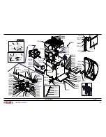
Page 43: ...126 100209 100170 100002 100081 100080 300019 300064 300064 100041 300093 100064 300020 100041 300362 100310 100031 200585 300296 300321 100126 300270 300101 300044 300101 300011 100178 200183 300077 100127 100209 300016 300281 300059 100277 100249 100071 100071 100071 100070 100071 100070 100128 100129 100129 300428 100050 100050 300039 100116 300216 100031 100062 100379 100195 300215 100209 1001...

Page 44: ... 300221 300087 300099 100454 300284 300046 100275 300344 300045 300263 300047 100162 300122 100201 100053 100053 100177 300065 100354 300067 300260 100050 300083 300086 300085 300084 100087 100213 100258 300139 300079 300088 300080 300082 300091 100232 ...

Page 45: ... FLAT 8 POLES BLUE BROWN BLUE BLUE BROWN BROWN YELLOW GREEN BROWN BLACK GRAY CROSSOVER CABLE 8 pole GRAY ORANGE R3 R3 FUSE F2 500mA T FUSE F2 500mA T JP6 JP6 JP9 JP9 JP3 JP3 JP12 JP12 N M1 M3 C2 C1 M2 L L JP18 JP18 MICRO CARTER MICRO CARTER 1 2 3 BLUE YELLOW GREEN BROWN JP15 JP15 JP17 JP17 FUSE F3 2 5A FUSE F3 2 5A JP13 JP13 R2 R2 JP14 JP14 RS485 Espansione Inverter JP5 RS485 Espansione Inverter J...

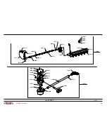
Page 46: ... 400005 400012 100220 100038 400027 100036 100258 100079 400053 100258 100036 100026 100042 100049 400100 400001 400077 100397 400053 100040 100079 100040 100079 100036 100030 100258 400099 400095 100258 100079 100277 300059 400105 100215 100090 100211 100018 100019 100013 100012 100013 100012 100032 200107 200116 200114 100030 100026 200113 200115 200106 100031 100026 100032 ...

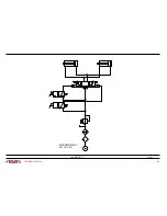
Page 47: ...47 solutions creator cod 400111 rev 0 PRESSIONE ESERCIZIO DA 1 5 A 12 bar ...

Page 48: ...G DECLARACIÓN DE CONFORMIDAD CE La Maison Hiermit bescheinigt das Unternehmen La Compañia M B Engineering srl VIA DELLA COSTITUZIONE 45 42015 CORREGGIO REGGIO EMILIA ITALY declare par la presente comme constructeur et depositaire du dossier technique la conformité du produit Hiermit Erklaert als Hersteller und Verwahrer der Technischen akte die Uebereinstimmung des produktes por la presente declar...

Page 49: ...Via della Costituzione 45 42015 Correggio RE Italy Tel 39 0522 644511 Fax 39 0522 644510 www mb re it info mb re it ...

Reviews:

Related manuals for WB 690