background image

1

2

Ø

Limit values

Service Data

Dimensions

138

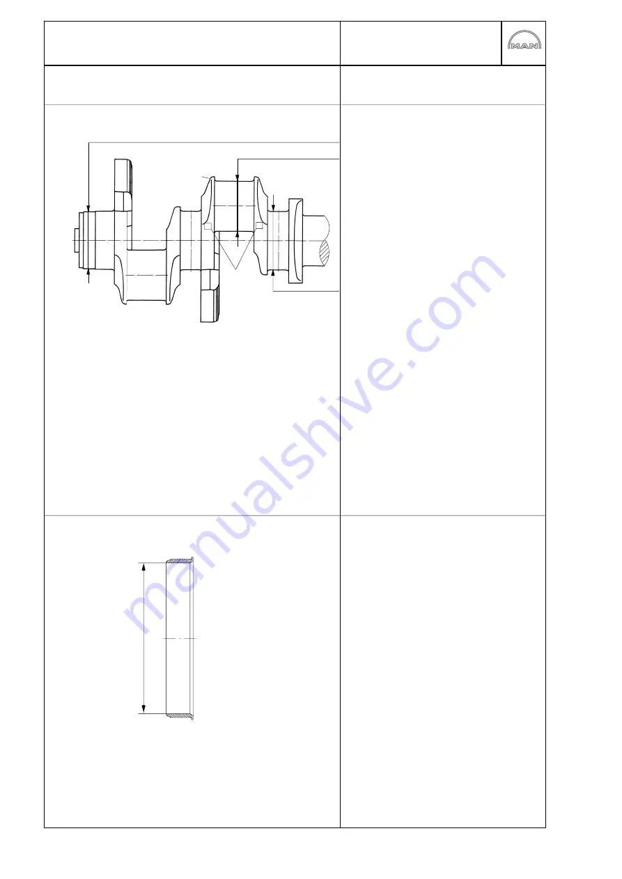
Crankshaft

Crankshaft front end 

(opposite end to flywheel)

99,985

100,020 mm

Standard size:

89.98

90.00 mm

undersize 

0.25:

89.73

89.75 mm

undersize 

0.50:

89.48

89.50 mm

undersize 

0,75:

89.23

89.25 mm

undersize 

1.00:

88,98

89,00 mm

Standard size:

103.98

104.00 mm

undersize 

0.25:

103.73

103.75 mm

undersize 

0.50:

103.48

103.50 mm

undersize 

0.75:

103.23

103.25 mm

undersize 

1.00:

102,98

103,00 mm

1 = Colour marking for size identification
of crank pin diameter
2 = Colour marking for size identification
of main bearing journal diameter

Undersize 0,25:

red

Undersize 0,50:

white

Undersize 0,75:

yellow

Undersize 1,00:

lilac

Permissible axial clearance of crankshaft:
0,190

0,322 mm

Bearing race for crankshaft, front end

Inner diameter: 99,907

99,942 mm

Summary of Contents for D 2842 LE 620

Page 1: ......

Page 2: ......

Page 3: ...MAN regulations otherwise the manu facturer s warranty will not apply For basic information on the fuels see the publication Fuels Lubricants and Coolants for MAN Diesel Engines You can find the appro...

Page 4: ...operation due to the sewing machine effect in particular if they are used between parts with different rates of linear expansion under heat e g aluminium and cast iron and leaks may then occur Exampl...

Page 5: ...ng coolant pump with high temperature and low temperature parts 44 Cleaning cooling system 51 Lubrication Changing oil filter 53 Removing and installing the oil cooler 54 Removing and installing repai...

Page 6: ...acing cylinder liners 125 Measuring piston protrusion 129 Attachments Removing and installing starter motor 130 V belts 131 Tensioning and changing V belt 132 Removing and installing speed pickup 133...

Page 7: ...model type D 2842 LE 620 as an example D The D at the start of the type classification stands for Diesel 28 The numbers 28 indicates that the power plant in question has a bore of 128 mm 4 The 4 mean...

Page 8: ...orised persons D The engine must be started and operated by authorised personnel only D When the engine is running do not get too close to revolving components Wear tight fitting working clothes D Do...

Page 9: ...nuine MAN parts only Installation of equally good parts from other suppliers may cause severe damage for which the workshop carrying out the work is responsible D Never operate the engine while it is...

Page 10: ...h hazard if the basic safety and hygiene related regulations are observed Health and safety regulations D Avoid prolonged excessive or repeated contact of old engine oil with the skin D Use a suitable...

Page 11: ...rail on the rail and on the cylinder head to the injector Keep away from the engine when it is running D Risk of injury When the engine is running the lines are constantly under a fuel pressure of up...

Page 12: ...inspection for any leakage or damage to the fuel system D Do not spray the high pressure cleaner direct onto the electric components or alternati vely keep them covered D Do not carry out any welding...

Page 13: ...akes off when connections are loosened from possible over coa ting these chippings must be carefully removed before finally loosening the screw con nection D The connection openings of all removed par...

Page 14: ...down the probable causes by asking specific questions examining and eliminating these causes one by one with the aid of the table and your own experience This helps to reduce repairs to those necessar...

Page 15: ...ged short to ground x x x x Engine oil viscosity unsuitable not suitable for ambient temperature lube oil qual ity does not comply with specifications x x Oil level in oil pan too high x Oil level in...

Page 16: ...sure system injectors defective clogged leaking coked x x x x o Fuel high pressure system pressure lines constriction cavitation leaking x x o x x x x o Fuel high pressure system high pressure pump wo...

Page 17: ...relation to the values measured on commissioning the engine D Charging pressure D Exhaust temperature D Coolant and lubricant temperature D Oil pressure and oil consumption D Smoke emissions The foll...

Page 18: ...aining damage and its causes If engines are not pressurised the risk of premature damage to bearing surfaces is very high because it takes a relatively long period of time for the lube oil drawn in fr...

Page 19: ...nkcase or from crankcase bores which may not be plugged can be detected immediately For this purpose mount the engine on an assembly dolly remove the oil pan and install a suitable oil collector under...

Page 20: ...Engine views D 2842 LE 620 18 7 1 2 4 3 5 6 7 1 2 4 11 9 10 8...

Page 21: ...Engine views D 2842 LE 620 19 In take pipe Turbocharger Starter motor Exhaust manifold Oil sump Tension pulley Rail Coolant pump Oil filter Oil dipstick 11 Oil separator valve for crankcase breather...

Page 22: ...haft High pressure pump lubrication Lubricating oil lines to exhaust turbochargers Oil return line from exhaust turbochargers Holes for main bearing lubrication Oil pump with oil pressure relief valve...

Page 23: ...ng oil lines to exhaust turbochargers Rocker arm lubrication Piston pin lubrication Spray nozzles for piston cooling and cam lubrication Camshaft bearing lubrication Oil intake pipe Oil pressure relie...

Page 24: ...Fuel diagram 22 2 3 1 4 1 2 3 4 8 7 9 3 4 10 10 5 6 Tank Fuel prefilter with water separator Injector Rail High pressure pump Fuel pump Fuel filter Fuel distributor Solenoid valve Glow plug...

Page 25: ...3 4 5 10 11 6 7 8 9 12 Overflow and vent pipe Filler pipe Positive pressure negative pressure valve Thermostat Coolant level in surge tank Engine crankcase Surge tank Water pump Coolant filler neck 11...

Page 26: ...up together with the plate is to be previously detached Fig 3 The graduated scale on the flywheel which is vis ible through the inspection hole in the flywheel housing is often difficult to access How...

Page 27: ...t of the rpm sensor and pull out the rpm sensor No marking may be visible Fig 7 If the engine is now turned back to 69 before TDC 2 markings must be visible If both markings are visible then fit the r...

Page 28: ...h escaping fuel in a suitable container Fig 1 Unscrew the union nuts of the high pressure lines between the rail and high pressure pump Fig 2 Unscrew the union nuts of the high pressure lines between...

Page 29: ...pump and to fuel distributor Undo all the electrical connections to the high pressure pump Caution All connections and removed parts are to be closed immediately with suitable caps The lines contain...

Page 30: ...re pump Fig 5 Tighten the mounting bolts in the sequence and method specified pos 1 4 Order of tightening 1 2 3 4 in the steps 1 Initial torque 10 15 Nm 2 final torque 65 70 Nm Check the base fitting...

Page 31: ...jam D the high pressure pump drive to break The lines contain fuel Catch escaping fuel in a suitable container Fig 1 D Close shutoff valve from tank to engine Caution Before the high pressure lines a...

Page 32: ...essure lines with WAF 17 union nuts must be replaced High pressure lines with WAF 19 union nuts may be reused Injection lines must be fitted without tension Tightening torques for high pressure lines...

Page 33: ...s Dirt in the injection system causes D injectors to jam D the high pressure pump drive to break The lines contain fuel Catch escaping fuel in a suitable container Fig 1 Remove the rail pressure senso...

Page 34: ...ressure pump drive to break The lines contain fuel Catch escaping fuel in a suitable container Removing injectors D Close shutoff valve from tank to engine D Removing rail see page 29 D Draining off c...

Page 35: ...ove coolant bleed pipe rail carrier and leak oil pipe Fig 5 and Fig 6 Unscrew the mounting bolt of the connector fit ting and pull the pressure pipe fittings out of the cylinder head Fig 7 Unscrew the...

Page 36: ...opened Caution Immediately close off the connection openings of the injector with suitable caps see page 172 and place in the storage sleeve Clean the injector seat in the nozzle bushing Fitting inje...

Page 37: ...Fig 6 Final tightening 20 Nm Angle tightening 905 Check tightness of injector pressure pipe and leak oil line Caution After the injectors have been installed al ways check to ensure that the injector...

Page 38: ...Install rail carrier coolant bleep pipe and cable har ness for injector Connect cable harness to the injectors Tightening torque 1 5 Nm Fig 16 Fit valve cover with seal and tighten mounting bolts D I...

Page 39: ...when the engine is switched off Close shut off valves between engine pre filter and tank D Disconnect plug D Remove filter bowl and filter element D Wet seal on new filter with fuel D Screw on filter...

Page 40: ...wrench unscrew it by hand and take it off D Moisten the seals on the new filter cartridge with fuel D Screw on the filter cartridges and tighten them vigorously by hand D Bleeding the fuel system D Ch...

Page 41: ...ug with new sealing ring until it stops at the counter nut and align it with fuel line Connect up fuel line and electric connection Tighten counter nut Checking solenoid valve for leaks Remove fuel li...

Page 42: ...wn The cooling system of the engine is to be filled with a mixture of drinking water from the mains and anti freeze based on ethylene glycol and or anticorrosion additive See Publication Fuels Lubrica...

Page 43: ...ermostats as fol lows D Suspend the thermostat in a bowl of water D Heat up the water D Use suitable thermometer to ascertain the opening start and compare it with the set point value given in Service...

Page 44: ...ing or repairing a coolant pump ascertain D whether the cooling circuit shows visible and recurring signs of coolant loss if yes D whether the coolant loss is caused by spillage from the expansion tan...

Page 45: ...rankcase arrows Fig 3 The water pump can then be fixed to the protruding pins Fit the mounting bolts There is a screw for removing the pins special tool see page 171 no 42 This screw has a left handed...

Page 46: ...p HT circuit 8 Mechanical seal 51 06520 0099 9 Counterring complete 51 06520 0100 10 Impeller for coolant pump LT circuit 11 Splash shield 12 Mechanical seal 51 06520 0096 13 Coolant pump bearing 14 D...

Page 47: ...M8 are pro vided Fig 7 Note Remove bolt from low temperature part Fig 1 item 5 Align water pump housing on a suitable and stable surface Use a suitable mandrel to press the water pump shaft together...

Page 48: ...ring shaft Fig 10 Turn water pump housing over Press in new mech anical seal with press fitting sleeve special tool until it stops Observe installation note for seal on page 50 Fig 11 Press in counter...

Page 49: ...l tool until it stops Observe installation note for seal on page 50 Fig 14 Lay coolant pump gasket on pump housing Fig 15 Carefully fit low temperature suction part to high temperature pump housing To...

Page 50: ...special tool Fig 17 Press in new mechanical seal pos 6 with press fitting sleeve special tool until it stops Observe installation note for seal on page 50 Fig 18 Slowly press impeller on to bearing sh...

Page 51: ...Repairing coolant pump with high temperature and low temperature parts 49 Fig 20 Fit new pump cover and press it into housing using a suitable pressing tool Attach water pump with new seal see page 4...

Page 52: ...e coolant pump housing is in perfect condition If the bore shows even the slightest scoring or other minor damage a sealing bead of Dirko Transparent Part No must be applied to collar Fit the seal wit...

Page 53: ...shed immedi ately during the cleaning operation c Fill coolant circuit with a mixture of hot water min 50 C and Henkel P 3 neutrasel 5265 detergent 1 5 by volume 5266 5225 Kluthe Hakopur 316 refer to...

Page 54: ...h a mixture of potable tap water and anti freeze with at least 40 by volume refer to Publication Fuels Lubricants Filler caps and service valves of cooling system The rubber seals on the filler caps a...

Page 55: ...can and oil filter are filled with hot oil Risk of burns and scalding Fig 2 Remove mounting bolt of filter bowl Take off filter bowl and clean it internally Fig 3 Insert new filter element and fit fil...

Page 56: ...er housing cover with fitted oil cooler The 10 marked screws hold the oil cooler Only loosen these screws after removing the housing cover Fig 3 Check both oil cooler for damage and if necessary repla...

Page 57: ...cient capacity here to prevent oil from overflowing Caution Old oil is hazardous waste Observe safety instructions for the pre vention of environmental damage Remove oil pan Caution Oil pans are awkwa...

Page 58: ...ious oil pump versions are possible Repairing oil pump Fig 6 Fit the oil pump in a vice use protective jaws Remove oil pump cover Fig 7 Pull the driven oil pump wheel from the casing Check the toothed...

Page 59: ...tion on the dial gauge Installing oil pump Fig 11 Tighten the mounting bolts with the prescribed torque D Before installing check whether the oil pump run smoothly and then fit it them free of ten sio...

Page 60: ...ter until oil pressure warning lamp goes out oil pres sure gauge indicates pressure Then restore elec tric connection to speed pickup Then start the en gine and allow it to run at medium speed for a f...

Page 61: ...oil injection nozzle valve Fig 2 Unscrew the oil injection nozzle valve from the body of the oil injection nozzle The valve plunger must move up and down easily If the valve plunger sticks or jams re...

Page 62: ...ust reach the entry bore hole of the cooling duct in the piston crown and cams without hindrance Bent oil injection nozzles must on no account be repaired Turn the engine The crankshaft drive or pisto...

Page 63: ...he correct position Fig 1 Block the crank gear The illustration shows a special tool that is to be fitted to the inspection port of the flywheel housing Fig 2 Loosen the securing screws of the vibrati...

Page 64: ...4 Loosen the mounting bolts of the cover Fig 5 Remove the cover Only replace the front crankshaft gasket as a com plete unit i e replace the bearing race and the radial shaft sealing ring Replacing th...

Page 65: ...the press in sleeve on the adapter with collar nut and thrust washer and in Fig 9 Note The bearing race can also be mounted when the cover is fitted Replacing the radial shaft sealing ring Fig 10 To e...

Page 66: ...Tighten the mounting bolts with the prescribed torque Fit cranking device Fit and tension V belts see page 132 Fig 13 and Fig 14 During assembly the delivery start indicator on the vibration damper ma...

Page 67: ...le lifting gear Danger The flywheel is heavy Use lifting gear Fitting the flywheel Fig 3 Insert the guide pins Coat the sealing face on the inside of the flywheel with Antipor 46 sealing compound Plac...

Page 68: ...ured on the contact surface of the starter motor toothed wheel prior to shrinking on the starter motor toothed wheel If the required value is exceeded replace the flywheel Engage the flywheel at the h...

Page 69: ...with the special tool or a screwdriver Fit shaft sealing ring Fig 2 When fitting a new shaft seal you should also ex change the bearing race of the flywheel Insert the new shaft sealing ring into the...

Page 70: ...ace to be exchanged using a puller special tool see Page163 no 12 2 Fig 2 Insert the new bearing race in the drift special tool in such a way that the inner bevelled side faces the flywheel when fitte...

Page 71: ...llest damage causes leaks The sealing lip and the bearing race of the flywheel must not be coated with oil or other lubricants On fitting the new sealing ring always replace the bearing race alongside...

Page 72: ...lines see page 32 Fig 2 Remove the mounting bolts from the charge air pipe Fig 3 Remove the mounting bolts from the intake pipe Remove the intake pipe Installing intake pipe Fig 4 Place intake manifol...

Page 73: ...e exhaust pipe is heavy Before unscrewing all securing bolts if appropriate replace 2 bolts by stud bolts as guides The stud bolts with thread M10 have been pro duced by MAN Remove exhaust pipe Instal...

Page 74: ...arly mechanical damage If engine performance is not satisfactory Correct adjustment of the delivery start valve clearance speed adjustment to full load stop In addition the following are to be checked...

Page 75: ...ssibly steep inclines The crankcase pressure is to high This may be caused by a defective oil separator valve or piston ring wear Compressor carbonization This can occur when the charge air temperatur...

Page 76: ...re A general set point value for charge air pressure cannot be given as the installation conditions have a bearing on this The value ascertained during the commissioning of the engine and noted in the...

Page 77: ...arger 75 Removing turbocharger Fig 1 Remove the charge air elbow and the charge air pipes leading to the turbocharger Fig 2 Detach intake neck Fig 3 Remove oil pressure line from turbocharger Fig 4 Re...

Page 78: ...urbocharger Fig 6 The turbocharger is fitted in reverse order On assembly new gaskets and new self locking nuts are to be used Before connecting the oil supply line fill the bear ing housing with fres...

Page 79: ...ween the two is the axial play Change turbocharger if axial clearance is ex ceeded Radial clearance Radial clearance is measured only on turbine end with dial gauge or feeler gauge Fig 2 Dial gauge Ap...

Page 80: ...ructions for the preven tion of environmental damage Fig 2 Back off the valve adjusting screws Release and remove the cylinder head bolts in re verse order of tightening Remove the rocker arm bearing...

Page 81: ...cylinder head is fixed in position with 2 fitting sleeves Fig 6 Check the tappet push rod for deformation When inserting the tappet push rods ensure that they fit in the socket of the valve tappet Ins...

Page 82: ...te To avoid any distortion between the cylin der heads and exhaust pipes we recom mend proceeding as follows D Place the cylinder head seals and cylinder heads in position D Screw in the head bolts a...

Page 83: ...er head seal Tighten the cylinder head bolts with the engine cold i e the crankcase is hand warm or colder Before inserting the cylinder head bolts apply engine oil to the thread not the threaded hole...

Page 84: ...lieved of load The valves of the synchronised cylinder are then on overlap Fig 3 D 2842 LE 620 Valves overlap in cylinder 1 12 5 8 3 10 6 7 2 11 4 9 6 7 2 11 4 9 1 12 5 8 3 10 Adjust valves in cylinde...

Page 85: ...and bolt the rocker arm bearing housing onto the mounting plate The exhaust valve rocker arm shaft has a tapped hole Screw adapter and impact puller into this tapped hole Fig 2 Pull out the exhaust v...

Page 86: ...ig 7 Recesses in the rocker arm shafts serve to ac commodate the cylinder head bolts Align the rocker arm shafts so that the holes for the cylinder head bolts are kept free Lightly oil the shafts and...

Page 87: ...part A for the exhaust side shaft into the guide plate ensuring that the alignment pins fit into the shaft bores Fig 11 Drive the rocker arm shaft fully home into the bear ing housing Fig 12 Insert pr...

Page 88: ...13 Dismantling and assembling the rocker arm mechanism 86 Fig 13 Remove the press in tool Check the rocker arms for ease of movement and axial play...

Page 89: ...ssure fork Extension for pressure fork Assembly cartridge for retaining wedges Sleeve with large diameter for 2 valve cylinder head Sleeve with small diameter for 4 valve cylinder head Depending on th...

Page 90: ...ing wedges Fig 6 Attach pressure fork and press down as far as possible with the mounting cartridge Press the knurled grip arrow down turning a little if necessary Fig 7 Release the pressure fork slow...

Page 91: ...emove the valves Clean parts Inspect the valve stem for pitting and wear Inspect the valve guides for wear if necessary measure internal diameter see Service Data with a plug gauge Inspect the valve s...

Page 92: ...ve plate recess exhaust valve Fig 14 Turn the cylinder head over and secure to the mounting plate Insert the washers for the valve springs Fig 15 Mount the insertion sleeve for the valve stem seals sp...

Page 93: ...ring seats Fig 19 Fit guide sleeve over the valve spring for cen tring Mount anchor plate and guide sleeve from the special tool kit Insert the retaining wedges in mounting cartridge Fig 20 Insert the...

Page 94: ...tapers are correctly seated as tapers which spring out may cause serious engine damage Measuring valve recess Fig 22 Position the dial gauge with its holder on the cylin der head Set the tip of the di...

Page 95: ...ve guides Fig 2 Press out the valve guide from the combustion chamber side with press in punch Fig 3 Lubricate the new valve guide and press in with the press in punch and press in sleeve from the roc...

Page 96: ...seat machining tool valve seat turning tool to cut a groove approx 3 4 mm wide in the valve seat insert Insert an internal puller into the cut groove and tighten Fig 2 Note To avoid damaging the cyli...

Page 97: ...When the valve seat inserts are replaced the valve seats must also be refaced Note D After temperature compensation machine the valve seats D After machining clean the cylinder head and check for lea...

Page 98: ...Jaccard lever 15 Guide ball 16 Feed nut with mm scale Fig 2 Select a suitable guide mandrel screw it in and tighten with a fork wrench Note For extreme precision work the guide mandrel must fit snugl...

Page 99: ...rank vigourously and steadily but under no circumstances against the direction of turning as this may cause the carbide cutting edge to break off Fig 6 Once the valve seat has been cleanly machined re...

Page 100: ...ve recess serves as the reference value Fig 9 The valve seat insert must be changed if as a re sult of the cylinder head interface and the valve seat insert having been machined the theoretical valve...

Page 101: ...guide free of abrasive paste Fig 3 The valve seat must have a faultless contained grinding pattern The grinding pattern width is correct if the valve seat insert is in order Valve tapered area Valve s...

Page 102: ...the oil pan Loosen the mounting bolts of the oil pan Fig 3 Danger The gear case is heavy Use lifting gear To facilitate assembly two bolts on opposite sides can be replaced by guide pins M12x1 5 Two l...

Page 103: ...the bolts with the prescribed torque Tighten the mounting bolts of the oil pan Clean gasket residues from the sealing surface of the timing case cover Screw the timing case cover on with a new seal Se...

Page 104: ...truck Fig 1 Turn the engine upside down so that the valve tappets do not obstruct removal of the camshaft Fit inserting mandrel special tool to the camshaft Carefully remove the camshaft at the drive...

Page 105: ...carefully Caution Do not damage the bearings Fig 4 In doing so note the marking of the crankshaft and camshaft toothed gear Fig 5 If the camshaft cover in the crankcase has been removed insert it as f...

Page 106: ...iver for the revcounter Set the dial gauge to 0 Fig 7 Use a suitable lever to press the camshaft as far as it will go on the timing case Press the camshaft forwards against the dial gauge sensor as fa...

Page 107: ...ixed stop Double sided guide bush Press out plate Press out camshaft bearing bush of bearings 2 3 and 4 Fig 3 Use the special tool see Fig 2 to pull out bear ings 2 3 and 4 from the counter flywheel s...

Page 108: ...ractor special tool to pull out the cam bearing bush of bearing 7 from the fly wheel side Fig 7 Pull out the bearing bush Press out camshaft bearing bushes of bearings 5 and 6 Fig 8 Press out the bear...

Page 109: ...onto the shaft and insert in bearing bush 6 Here insert the guide bush with the larger diam eter in the bearing hole and let the spring loaded balls lock into the oil holes The groove of the shaft mu...

Page 110: ...5 and 6 Press in plate for bearing bush 7 Press in the camshaft bearing bush bearing 2 Figs 12 and 13 Place the bearing bush on the press in plate Caution D One oil hole of the bearing bush must be fi...

Page 111: ...ter in the bearing hole and let the spring loaded balls lock into the oil holes The groove of the shaft must then face upwards Apply the press in plate with fitted bearing bush Fig 17 Use a soft hamme...

Page 112: ...s in plate is fixed in place by the groove so that the oil holes line up after pressing in Fig 20 Use a soft hammer plastic or copper to drive the bearing bush into bearing 3 as far as it will go To f...

Page 113: ...the position of the shaft lock into the oil hole Insert the shaft up to the stop into the press in plate bearing 2 and press out plate bearing 3 Caution Do not twist the fixing from the groove The gr...

Page 114: ...d 4 Insert the guide bush with large diameter in bearing 7 The groove of the shaft must then face upwards Fig 29 Use a soft hammer plastic or copper to drive bearing bush 6 in as far as it will go To...

Page 115: ...of the press in plate D The bearing bush must be seated up to the stop on the press in plate Fig 32 The oil holes are covered in that the press in plate is fixed in position by the groove of the shaft...

Page 116: ...in der Set the valve clearance of the 1st cylinder cor rectly Fig 2 Turn engine over with cranking device until the valves of cylinder 1 are in cross over Turn the engine back to approx 50_ before TDC...

Page 117: ...ng cover Note Crankshaft bearing no 1 is located on the opposite side of the flywheel Fig 3 Gradually loosen the securing bolts of the crank shaft bearing cover from inside to out and un screw Remove...

Page 118: ...ankcase paying attention to the numbering Caution If new bearing shells are used pay atten tion to the corresponding repair stage Oil the contact surfaces of the bearing shells and insert the cranksha...

Page 119: ...al gauge to the crankshaft D Move the crankshaft back and forth in axial direction and read off the clearance from the dial gauge D If the permitted axial clearance is exceeded replace the main bearin...

Page 120: ...d with the connecting rod big ends arrange them in corresponding order Do not place the conrod bearing covers on the cracked faces Caution If their cracked surfaces are damaged the connecting rods mus...

Page 121: ...repairs to the conrod journals use bearing bush of the corresponding repair level Fig 6 Insert the bearing bushes in the conrod or conrod bearing cover so that they are flush Caution The rod shell ha...

Page 122: ...olts must be replaced After inadvertent attachment of cracked conrods and conrod bearing covers that do not belong together the parts must not be reused Fig 11 Turn the engine slowly The conrods and o...

Page 123: ...Remove piston and place to one side Measure conrod foot bore base hole Fig 3 Insert the new conrod bearing and fit the cap Tighten bolts according to regulation Measure bearing bore hole with an inte...

Page 124: ...location of conrod and twisting of piston pin eye to bearing bush bore hole In the case of deviations beyond the tolerance range replace conrod Fig 6 Place piston on the conrod Caution The recess for...

Page 125: ...Apply piston ring wrench to piston ring joint and disengage the piston ring from the piston ring grooves Note The coiled spring expanders mean that the oil scraper ring has greater tangential ten sion...

Page 126: ...facing upwards Checking piston ring axial clearance Fig 7 Determine the piston ring clearance in each piston ring groove at various points using a feeler gauge To do so press the piston ring fully int...

Page 127: ...cylinder liners Fig 2 Mark the cylinder liner position relative to the en gine so that it can be reinstalled if reused Insert the cylinder liner extractor apparatus into the cylinder liner taking car...

Page 128: ...126 Fig 5 Set the cylinder liner down in an upright position Remove the O rings Number cylinder liners in order of installation Fig 6 Remove the O rings from the crankcase Clean the seat for the cyli...

Page 129: ...er measure the cylinder liner protrusion at no less than 4 different points Specified values see Service Data Fig 8 The cylinder liner protrusion is the difference be tween the collar height and the c...

Page 130: ...pressure until the liner is seated in the crankcase recess Note To verify that the O rings are correctly seated after the cylinder liners are fitted check the liner protrusion with special tool as fol...

Page 131: ...n to be measured to TDC Apply the dial gauge bracket with dial gauge to the crankcase gasket surface Set the dial gauge to 0 Fig 2 Carefully swing the dial gauge bracket around while raising the tip o...

Page 132: ...ether it can move freely If necessary clean piston using a brush dipped in fuel and regrease it Check the flywheel ring gear for wear and damage Turn over engine by hand once paying particular attenti...

Page 133: ...d to disengage This will cause the indica tor to move upwards If pressure is maintained after the spring has dis engaged a false reading will be obtained Reading of tension D Read of the tensioning fo...

Page 134: ...ater pump tension pulley D Remove fixing bolts D Release lock nut D Turn adjusting nut until the V belt is correctly tensioned D Retighten lock nut and fixing bolts To change the V belt turn back the...

Page 135: ...ickup are fitted to the flywheel housing at bottom right Only the lower transmitter is installed on engine D 2842 LE 620 For removal disconnect cable from plug connec tion arrow Fig 2 Remove mounting...

Page 136: ...134...

Page 137: ...135 Service Data...

Page 138: ...Direction of rotation viewed on flywheel anti clockwise Firing order 1 12 5 8 3 10 6 7 2 1 1 4 9 Power based on DIN ISO 3046 D 2842 LE 620 662 kW 900 PS at 2100 rpm Lubrication Pressure circulation f...

Page 139: ...145 04 mm 1 0 mm 145 50 145 54 mm Cylinder liner standard size 153 694 153 757 mm with larger outside diameter 0 5 and 1 0 mm 154 194 154 257 mm standard size 10 030 10 050 mm with more flange height...

Page 140: ...98 104 00 mm undersize 0 25 103 73 103 75 mm undersize 0 50 103 48 103 50 mm undersize 0 75 103 23 103 25 mm undersize 1 00 102 98 103 00 mm 1 Colour marking for size identification of crank pin diame...

Page 141: ...ze 0 75 yellow Undersize 1 00 lilac Main bearing Data for wall thickness and bearing inner diameter also apply to the align ment bearing Standard size 3 455 3 467 mm undersize 0 25 3 580 3 592 mm unde...

Page 142: ...m undersize 0 25 0168 0169 mm undersize 0 50 0170 0171 mm undersize 0 75 0172 0173 mm undersize 1 00 0174 0175 31 01 31 04 mm Data for wall thickness and bearing bore see main bearing Mounting bolts f...

Page 143: ...r gear ring Flywheel 432 490 432 645 mm Internal gear ring 432 000 432 155 mm Interference 0 335 0 645 mm Installation temperature 200 230_C m 54 2 kg with gear ring J 1 98 kgm2 Number of teeth Z 160...

Page 144: ...Conrod bearings Standard size 2 463 2 473 mm undersize 0 25 2 588 2 598 mm undersize 0 50 2 713 2 723 mm undersize 0 75 2 838 2 848 mm undersize 1 00 2 963 2 973 mm Spread 0 6 1 5 mm If signs of wear...

Page 145: ...bolt diameter 45 994 46 000 mm 127 870 127 880 mm Max difference in weight per engine pis ton set 100g Piston ring grooves 3 695 3 725 mm 3 040 3 060 mm 4 02 4 04 mm Piston rings 1st ring keystone ri...

Page 146: ...e guide bore in cylinder head 15 000 15 018 mm Valve guide outside diameter 15 028 15 046 mm standard 113 9 114 mm observe specified dimensions for valve recess and injector projection Valve seat inse...

Page 147: ...mbol 51 90490 0041 0070 new 259 259 5 mm max 261 5 mm 51 90490 0042 0071 new 197 5 198 mm max 200 mm Valve recess Intake valve 8 963 8 977 mm Exhaust valve 8 950 8 964 mm Valve recess 0 70 1 00 mm Val...

Page 148: ...27 961 27 97 mm Rocker arms 28 005 28 021 mm Rocker arm radial clearance 0 035 0 06 mm Camshaft Replace if there are traces of wear Camshaft axial clearance 0 20 0 90 mm Wear limit 1 5 mm 69 910 69 9...

Page 149: ...ions 147 Camshaft bearing 70 000 70 030 mm for bush 7 V 12 bush at timing case end Ventilst el Bore in crankcase 20 000 20 021 mm 19 944 19 965 mm Valve clearance Valve clearance cold engine Einlassve...

Page 150: ...xhaust closes in TDC 4 exhaust valve opens 60 before BDC 5 intake valve closes 36 after BDC 6 Exhaust open for 240 7 Inlet open for 240 The degrees specified refer to the crank shaft angle Compression...

Page 151: ...ousing 22 000 22 021 mm Radial clearance 0 060 0 091 mm Press on force 12200 N Housing depth 34 000 34 039 mm Axial clearance 0 050 0 128 mm 33 911 33 950 mm 14 5 14 7 mm Gear width 38 mm Shaft 17 930...

Page 152: ...in drive gear 21 870 21 885 mm Press on force 12000 N Backlash Drive wheel and crankshaft wheel 0 099 0 451 mm Oil pump delivery rate The speeds are pump speeds Oil pump speed engine speed x 0 977 i...

Page 153: ...0 035 0 064 mm Bore in hub belt pulley 23 007 23 020 mm of bearing shaft 23 048 23 061 mm Interference 0 028 0 054 mm Bearing seat in housing HT 35 994 35 010 mm of bearing 34 989 35 000 mm Interfere...

Page 154: ...Limit values Service Data Dimensions 152 Turbocharger D 2842 LE 620 K33 4267 OPAKB 22 90 GDAYK Axial clearance K33 max 0 16 mm Radial clearance K33 max 0 45 mm...

Page 155: ...Limit values Service Data Dimensions 153 Fuel system Injectors Manufacturer Bosch Number of holes 7 High pressure pump Bosch CP2V4 Governor Elektronic Diesel Control EDC Type EDC 7...

Page 156: ...Nominal power 6 6 kW Nominal voltage 24 V V belts Powerband Change damaged V belts cracks wear oil Measuring tension withtension tester Tensioning forces according to the kg graduation on the tester D...

Page 157: ...0 Nm Inspection port cover to gear case M8 12 9 40 Nm Timing case cover to crankcase M8 10 9 25 Nm 5 1 8 7 4 2 3 6 Crankshaft bearing cover to crankcase M18x2 Initial torque 300 330 Nm Angle tightenin...

Page 158: ...drain plug to oil pan M26x1 5 80 Nm Oil jet to crankcase M14x1 5 70 Nm Exhaust Intake pipes Exhaust manifold to cylinder head M10 Initial torque 60 65 Nm Angle tightening 90 1005 Oil cooler to oil fil...

Page 159: ...or retainer Initial torque 25Nm Angle tightening 90_ 5 Mounting bolt for connector to injection line Final torque 20 Nm Angle tightening 90_ 6 High pressure line Danger High pressure lines with WAF 17...

Page 160: ...0 M8x1 23 0 35 0 40 0 M10 45 0 65 0 75 0 M10x1 25 45 0 65 0 75 0 M10x1 50 0 70 0 85 0 M12 75 0 105 0 125 0 M12x1 5 75 0 110 0 130 0 M12x1 25 80 0 115 0 135 0 M14 115 0 170 0 200 0 M14x1 5 125 0 185 0...

Page 161: ...htening schedule 1 by 90 1 4 turn Note The cylinder head bolts to be retighte ned must not be loosened they are to be tightened further from their current position by 90 1 4 turn Remove the sticker Fi...

Page 162: ...st side Tightening schedule 2 Retightening the cylinder head bolts following a repair Engine cold or warm After the first 10 to 20 hours of operation following a repair tighten the cylinder head bolts...

Page 163: ...161 Special tools...

Page 164: ...Special tools 162 1 2 3 4 5 6 7 8 9 10 11 11 1 11 2 12 12 1 12 2 13 14...

Page 165: ...A RED15 10 PLA3C 2x reducing connection D8134A RED22 15 PLA3C 1x screw plug D813A VKA 10A3C 80 99620 0033 81 98130 0614 82 98130 0174 82 98130 0194 82 90310 0023 8 Mounting plate for cylinder head and...

Page 166: ...Special tools 164 15 1 15 2 15 3 15 4 15 5 1 2 7 15 6 3 4 5 6 15 7...

Page 167: ...15 4 Connecting piece for compression recorder 80 99607 0158 15 5 Mounting tool for valve springs and tapers set Mounting tool Extension Centring plate Mounting tool Mounting cartridge Guide sleeve He...

Page 168: ...Special tools 166 16 16 1 16 2 16 3 16 6 17 16 4 16 5 16 7 18 19 20 1 20 2 21 22 23 24 25 26 27 28...

Page 169: ...cap dia 62 2 mm 51 91606 0045 19 Hexagon bolt wrench 5 with transverse handle for valve clearance setting 08 06125 9035 20 1 Torque wrench 6 50 Nm for valve clearance setting 08 06450 0006 20 2 Ring...

Page 170: ...Special tools 168 3 1 4 29 5 6 2 29 30 31 32 33 34 35...

Page 171: ...Dial gauge bracket 08 71000 1205 80 99605 0197 80 99605 0179 80 99605 0180 80 99605 6006 80 99605 0172 30 Press on measuring plate 80 99605 0195 31 Fitting sleeves 51 91701 0247 32 Inserting mandrel...

Page 172: ...Special tools 170 36 37 38 39 42 40 41 44 2 44 1 44 43 1 43 2 43 3 43 45 46...

Page 173: ...sing for pressing on the V belt pulley 80 99606 0628 41 Support for coolant pump housing for pressing in the V belt pump shaft 80 99606 0629 42 Press in mandrel for axial face seal 80 99617 0191 43 43...

Page 174: ...2 Adapter 08 06139 9029 49 3 Extension 08 06139 9007 49 4 Magnetic lifter for removing pressure pipe fittings 80 99639 0009 49 5 Wrench socket for injector cable connection 08 06141 0700 49 6 Wrench s...

Page 175: ...conjunction with items 54 55 56 Insert WAF 19 80 99603 0311 57 Support 80 99606 0585 Tightening main bearing bolts in conjunction with items 54 55 58 Insert WAF 27 80 99603 0312 59 Support 80 99606 0...

Page 176: ...general notes 81 Cylinder liner 137 Cylinder liners 125 D Drain engine oil 55 E Engine Lubrication D 2842 LE 620 136 Engine lubrication D 2842 LE 620 149 E Engine oil filling capacities D 2842 LE620 1...

Page 177: ...11 Safety regulations Special instructions when working on the common rail system 9 Service Daten 135 161 Solenoid valve 39 Special tool for removing injectors 172 Special tools 161 170 Starter motor...

Page 178: ...176...

Page 179: ......

Page 180: ......

Reviews: