


6
6
7
Setting valve clearance
99
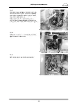
Fig. 5
Push feeler gauge between valve stem and rocker
arm. Loosen lock nut (17 mm) and turn adjusting
screw with screwdriver until feeler gauge can be
moved with slight resistance.
Tighten lock nut to the specified torque (see
“Service Data”) using screwdriver to prevent ad-
justing screw from turning. Check clearance again.
Fig. 6
Setting the valves can be considerably facilitated
by using the valve setting tool.
Fig. 7
Refit cylinder head covers with new gaskets.
Summary of Contents for D 2840 LE 301
Page 1: ......
Page 2: ......
Page 16: ...Notes 14...
Page 20: ...Engine views 18 Engine views D 2842 LE 301 9 10 11 12 9 8 6 5 4 3 2 1 13 14 15 16 17 18 6 7 8...
Page 150: ...Notes 148...
Page 151: ...149 Service Data...
Page 179: ...177 Special tools...
Page 180: ...Special tools 178 2 3 4 5 6 7 8 1 6 1 6 2 6 3 9 1 9 2 9 3 9...
Page 184: ...Special tools 182 21 22 25 25 2 24 25 1 26 27 1 27 2 27 20 1 19 2 19 1 20 2 19 20 28 23...
Page 186: ...Special tools 184 30 29 32 31 33...
Page 193: ......
Page 194: ......