background image

P 3 / 11 

R

epair

[3] DISASSEMBLY/ASSEMBLY

[3] -1. Poly V-belt 4-241
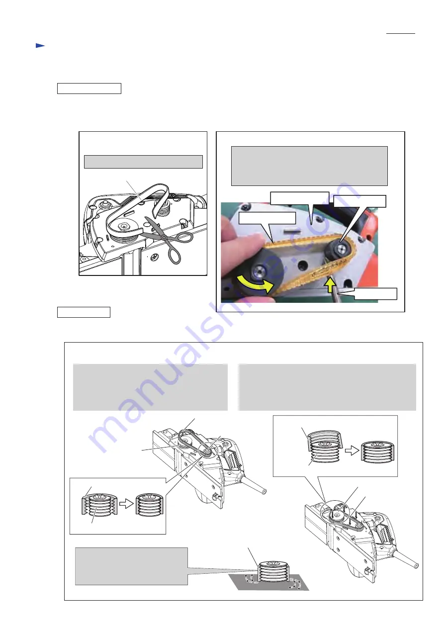
DISASSEMBLING

ASSEMBLING

(1) Disassemble Belt cover.

      Remove Belt cover and then remove Poly V-belt 4-241 as illustrated in 

Fig. 2

 in case of replacing the Poly V- belt only.

      In case of replacing Armature, Ball bearings or Drum, remove the Poly V-belt as illustrated in 

Fig. 2A

Cut Poly V-belt 4-241.

Fig. 2

Fig. 2A

Poly V-belt 4-241

Poly V-belt 4-241

Screwdriver

Bracket complete

V Pulley 4-20L

1. Engage all V-shaped ribs of Poly V-belt 4-241  

    with the grooves of V-pulley 4-20L (small one).

    And engage some of V-shaped ribs of the same

    of the Poly V-belt with the groove of V-pulley

    4-37 (large one).

2. Turn V-pulley 4-37 (large one), while pressing 

    the V-belt toward Bracket complete, until all 

    V-shaped ribs of Poly V-belt 4-241 with the grooves 

    of V-pulley 4-37 (large one). Now, Poly V-belt and 

    both of  V-pulleys engage each other.

Poly V-belt 4-241

V-Pulley 4-20L

Poly V-belt 4-241

Poly V-belt 4-241 

V-Pulley 4-20L

V-Pulley 4-37

Bracket complete

V-pulley 4-37

Poly V-belt 4-241

< Note >

Be careful,


not to push so deep that 

Poly V-belt 4-241 rubs against 

Bracket complete. 

Poly V-belt 4-241

V-pulley 4-37

(1) Mount Poly V-belt 4-241 as illustrated in 

Fig. 3

.

Fig. 3

1. Insert screwdriver under Poly V-belt 4-241.

2. Lever up the Poly V-belt with the screwdriver, 

    while turning any of  two V-pulleys.  

Now, Poly V-belt 4-241 is removed.

Summary of Contents for M1901B

Page 1: ...M1901B REPAIR MANUAL Power Planer OFFICIAL USE For ASC...

Page 2: ...rtion Main frame complete Amount Symbol of lubricant Portion to lubricate Apply lubricant VG100 to the parts designated with black triangle CAUTION Repair the machine in accordance with Instruction ma...

Page 3: ...ame of the Poly V belt with the groove of V pulley 4 37 large one 2 Turn V pulley 4 37 large one while pressing the V belt toward Bracket complete until all V shaped ribs of Poly V belt 4 241 with the...

Page 4: ...Pan head screw Carbon brush Brush holder cap Brush holder cap Bracket Double ended philips bit Bracket 4x18 Tapping screw 1 Unscrew six 4x18 Tapping screws with which Bracket complete is secured to M...

Page 5: ...aring 606ZZ is too tight to engage claw of 1R269 So fixing claw of 1R269 with Water pump pliers firmly remove Ball bearing 606ZZ Ball bearing 606ZZ Water pump pliers 1R269 Claw Ball bearing 6000ZZ Ass...

Page 6: ...tect hand against injury Turn counter clockwise for removing 1 Make the tip of claw shape because of too tight space between Ball bearing 608ZZ and Drum to engage the claws 12 3 6 9 Bit adapter assemb...

Page 7: ...000ZZ to the same of V pulley 4 37 side Refer to Fig 10 2 Mount Drum to Bracket And tighten V pulley 4 37 with Bit adapter Refer to Fig 9 V pulley 4 37 Bracket complete Note Enough to tighten V pulley...

Page 8: ...d Torsion spring 7 Knob 44 Knob 44 Flat washer 10 1 Remove Knob 44 as shown below 2 Front base can be separated from Main frame complete 3 Remove Scale label from Knob 44 because the numbers on Scale...

Page 9: ...been adjusted to Planning depth at 0 2 Stick Scale label on the Knob 44 while aligning 0 to the Triangle mark on the main fame Triangle mark fresh Scale label 2a If the removed Knob 44 is reused witho...

Page 10: ...erican Wire Gage Item No 2 2 1 1 Circuit of inside of Switch Symbol of electrical parts Note Noise suppressor is not used for some countries Viewing from Fan side AWG18 AWG18 Noise suppressor Power su...

Page 11: ...Insulated terminal of Switch that Noise suppressor does not interferes with setting of Switch when Noise suppressor is used Noise suppressor Switch Insulated terminals Field Pass Field lead wires thr...

Reviews: