background image

R

epair

P 5 / 8

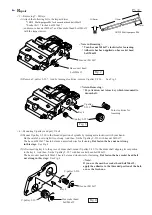
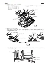
< 7 > Mounting handle R and L to main base.
         Joining handle R and L closely,  fix them
         ton main base with  8 pcs. of pan head screws M5x28.
          See Fig. 12.

Fig. 11

Fig. 12

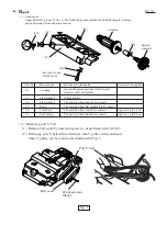
(2) Mount the armature to motor bracket. When mounting armature to motor bracket, align the coupling's spline with
      the spline of spindle, by slowly turning V-pulley 9-23L.

(3) Make sure that baffle plate has been assembled to motor housing. And mount motor housing to motor bracket
      with lifting up the armature body as illustrated in Fig. 11.

Fig. 10

Motor bracket

Slowly turn V-pulley 9-23L to
align the spline of spindle  with 
the couplings spline.

Coupling

Motor housing

Baffle plate

Lift up the armature body to avoid that the armature body
contacts field in motor housing.

8 pcs. of
 Pan head screw M5x28

Handle R

Handle L

Main base

Summary of Contents for KP312

Page 1: ...it and overload protector 120 15 1 700 690 2 450 KP312 Continuous Rating W Voltage V Cycle Hz Input Output Max Output W 220 Current A 50 60 50 60 230 10 11 2 200 2 200 1 040 820 3 000 3 850 KP312S Mod...

Page 2: ...ted in Fig 1 Fig 1 hex socket head bolt M10x40 86 67 46 74 68 69 Item No Descriptions Portions to be lubricated Amount to be applied Approx 4g 0 14 oz Approx 1g 0 04 oz 67 46 Flat washer 8 Coupling Wh...

Page 3: ...ft mount V pulley 9 39 7 to the drum shaft aligning its cut portion to the key 4 And then fix the V pulley 9 39 7 with hex socket head bolt M6x12 The hex socket head bolt M6x12 has to be turned clockw...

Page 4: ...nted to armature If not mount it And then mount coupling with aligning its spline with the armature s spline See Fig 9 2 Remove ball bearing 6202LLB with No 1R269 Bearing extractor See Fig 8 3 Remove...

Page 5: ...indle by slowly turning V pulley 9 23L 3 Make sure that baffle plate has been assembled to motor housing And mount motor housing to motor bracket with lifting up the armature body as illustrated in Fi...

Page 6: ...screw M4x60 2 pcs See Fig 13 2 Removed handle R The electrical parts can be replaced See Fig 13 10 Mounting bracket cove and main bracket Main bracket has to be closely mounted to bracket cover And bo...

Page 7: ...feature and over current relay Pass the following lead wires back side of switch opposite side of switch trigger Power supply cord black or brown Support unit s lead wires black and orange Pass the po...

Page 8: ...following lead wires with lead holder as illustrated Support unit s lead wire orange Lead wire of soft start circuit Hold support unit s lead wires black and orange with lead holder as illustrated Hol...

Reviews: