


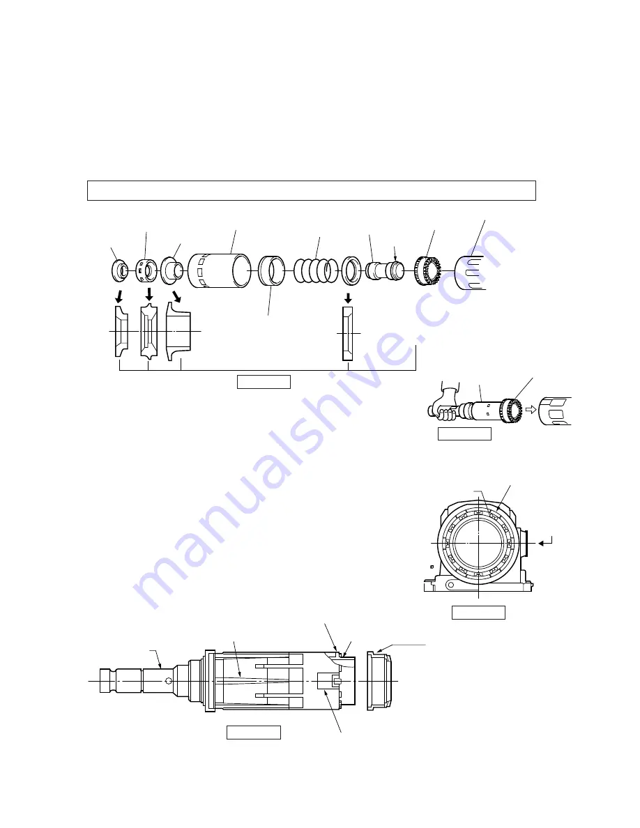
a. Set the parts described below into the crank housing.(See the figure 20.)
b. To set the spiral bevel gear 41, use the tool holder without mounting the lock sleeve for smooth setting.(See the figure 21.)
•Striker(mounted with O ring 34)
•Washer 45
•Ring 45
•Flanged sleeve 22
•Ring 22
•Spiral bevel gear 41
•Compression spring 46
•Slide sleeve
•Rubber ring
Note ) Use care that the washer 45, Flanged sleeve 22, rubber ring 24, ring 22 and striker have each direction.
Figure 20
Ring 22
Rubber ring
Flanged sleeve
Slide sleeve
Compression
spring 46
Striker
O ring 34
Spiral bevel
gear 41
Crank housing
Washer 45
Ring 45
Use care of each direction.
Figure 21
Figure 22
Figure 23
Tool holder
Spiral bevel gear 41
a. Assemble Tool holder B and Spiral bevel gear 41,
matching the cams of both parts.(See the figure 23.)
b. Turn Spiral bevel gear 41 to match dent portions on the can
with grooves on Crank housing. (see the figure 22.)
c. Match the cam on Lock sleeve A to the cam on Tool holder B.
(see the figure 23)
d. Match the flat portion of Lock sleeve A to the mounting side of Change
lever. fit the 6 protruded portions on Lock sleeve B to the 6 grooves on
Crank housing, and then insert the tool holder into Crank housing.
(see the figurt 23.)
12 dent portions
on the cam of the
spiral bevel gear 41
6 grooves on the
crank housing
Mounting side
of the change
lever
Tool holderA
6 protruded portions
on the lock sleeve B
Cam on the lock sleeve A
Cam on the tool holder B
Cam on the spiral
bevel gear 41
Flat portion of lock sleeve B
Assembling the tool holder
Inserting Tool holder(Same as HR4000C)


