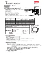
background image

COMPARISON CHART

Manufacturer

Model No.

Shank of bit

Continuous rating  Input (W)

No load speed (rpm)

Blows per min.(bpm)

Blows power (J)

Calculated by
MAKITA
Catalogue

Capacity

TCT. bit

Core bit

Changeable working mode from
Hammering&Rotating to
Hammering only mutually

Chuck system

Changeable setting angle of bit 

Electronic control 

Indication lamp for 
carbon brush change

Warning light for broken cord
and switch 

Overall length (mm) 

Weight (Kg)

MAKITA

MAKITA

Competitor A

Competitor B

Model B

Model A

HR4040C

HR4000C

Spline

SDS-Max

Spline

Spline

1,050

1,050

1,000

950

Amperage under 120 V 

9.6 A

9.6 A

8.8 A

9.4 A

230 - 450

180 - 360

120 - 320

1,250 - 2,500

1,600 - 3,200

1,100 - 2,850

230 - 450

1,250 - 2,500

6.7 J (4.9ft.lbs.)

6.7 J (4.9ft.lbs.)

6.7 J (4.9ft.lbs.)

6.7 J (4.9ft.lbs.)

5.1 J (3.8ft.lbs.)

6.3 J (4.6ft.lbs.)

5.7 J (4.2ft.lbs.)

__

Yes

Yes

Yes

Yes

40mm(1-1/2")

105mm(4-1/8")

40mm(1-1/2")

105mm(4-1/8")

40mm(1-1/2")

40mm(1-1/2")

 90mm(3-1/2")

 90mm(3-1/2")

Slide locking
in one action

Turn locking in
two actions

Slide locking
in one action

Turn locking in
two actions

Yes.12 x 30

°  

Yes.12 x 30

°  

No


No


Yes

Yes

Yes

Yes

Yes

Yes

Yes

Yes

Yes

Yes

Yes

Yes

470 (18-1/2")

455 (17-7/8")

455 (17-7/8")

448 (17-5/8")

measured by MAKITA

Catalogue

6.6 (14.6 lbs)

6.6 (14.6 lbs)

6.4 (14.1 lbs)

6.4 (14.1 lbs)

6.2 (13.7 lbs)

6.2 (13.7 lbs)

6.5 (14.3 lbs)

6.7 (14.8 lbs)

Standard 
equipment

Steel carrying case 

Cylindric form side grip

D-form side grip

Bit grease

Plastic caring case

Stopper pole

Summary of Contents for HR4040C

Page 1: ...t and overcomes competitors models Its brief benefits are Less operator s fatigue than competitors Less vibration and reaction toward hands Better feeling at drilling and hammering Quick change of ham...

Page 2: ...um hammering speed can be selected in accordance with materials or tools Setting at low speed ideal for such a light chipping works as scraping tiles removing bricks joint New Torque Limiting System T...

Page 3: ...4 A 230 450 180 360 120 320 1 250 2 500 1 600 3 200 1 100 2 850 230 450 1 250 2 500 6 7 J 4 9ft lbs 6 7 J 4 9ft lbs 6 7 J 4 9ft lbs 6 7 J 4 9ft lbs 5 1 J 3 8ft lbs 6 3 J 4 6ft lbs 5 7 J 4 2ft lbs __ Y...

Page 4: ...values when setting MAKITA HR4040C s data as 100 Chipped amount HR4040C HR4000C Model A 100 80 60 40 20 0 120 Operation without extension cord Operation with extension cord 100 100 95 95 110 110 HR40...

Page 5: ...position Figure 1 1 Change link is constructed to be slidden up and down Slide the change link upward with your finger See Fig 2 plastic hammer Lock button Change lever at neutral position Figure 2 S...

Page 6: ...embling disassembling The upper 2 screws Pan Head Screw M5x20 The other 4 screws Tapping Screw 5x20 4 Separate terminal black and white below from the controller see Fig 6 5 Remove pick up coil after...

Page 7: ...removed from the machine see Fig 4 Remove cuck cover by hitting its edge with plastic hammer slightly see Fig 5 2 Remove compression spring 50 after removing retaining ring S 50 And then remove crank...

Page 8: ...spare parts on tool holder in the order illustrated as per Fig 11 Remark The concave of leaf spring 39 has to come to that of the chuck ring when they are assembled see Fig 12 Tool holder Ring spring...

Page 9: ...ach other The concave with triangle mark inside of sleeve 46 The convex of the tool holder cap 4 5 Make sure whether the installed hammer bit can be locked firmly or not 6 Make sure whether the instal...

Page 10: ...alling fluoride ring 20 on impact bolt the ring comes stretched and its edge come protruding from the groove see Fig 19 2 In order to correct the deformation insert impact bolt with the fluoride ring...

Page 11: ...ht bevel gear 33 see Fig 22 Adjust the cams of lock sleeve A to the same of tool holder see Fig 23 Press tool holder into crank housing after the following process Face the flat part of lock sleeve A...

Page 12: ...0 sliding down 2 change keys And make sure whether the retaining ring S12 is assembled in the groove firmly see Fig 24 and 25 Note Be careful not to expand the retaining ring 12 too wide 4 Assemble sl...

Page 13: ...nner face of rod s hole 6 Outer face of impact bolt and tool holder side and crank housing side of rubber ring 19 7 Where the stem of straight bevel gear 10 is contact with torque limiter complete 8 L...

Page 14: ...Circuit Diagram 3 4 5 2 Switch Power supply cord Controller Brush holder Brush holder Support complete Black White Violet Black White Orange Orange Violet Red...

Reviews: