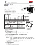


(10) Assembling tool holder section
1. Assemble the the spare parts of Fig.20 into
the crank housing.
< Note >
Straight bevel gear 33 can be installed into
the crank housing by pushing it with tool
holder smoothly. (see Fig.20)
2. Press urethane ring 35 and flat washer 35
on tool holder. And press ball bearing 6907
into bearing holder .
And then tool holder on which urethane
ring 35 and flat washer 35 are installed,
is pressed into the above bearing holder
and ball bearing 6907. (see Fig.21)
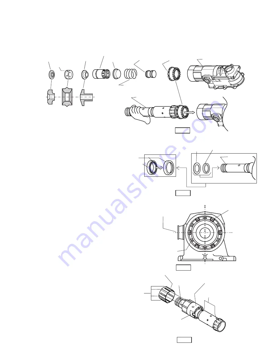
3. When pressing tool holder into straight
bevel gear 33, the cams on tool holder and the same
of straight bevel gear 33 have to engage each other.
(see Fig. 23)
* Adjust 12 concaves of straight bevel gear 33
to 6 concaves of crank housing by turning
straight bevel gear 33. (see Fig.22)
* Adjust the cams of lock sleeve A to the
same of tool holder. (see Fig.23)
* Press tool holder into crank housing after
the following process.
- Face the flat part of lock sleeve A to the
hole for change lever setting.
- Engage 6 convexes of lock sleeve B with
6 concaves of crank housing.
(see Fig.22 and 23)
Washer 16
Rubber ring 19
Sleeve 16
Slide sleeve 16
Ring 33
Compression spring 33
Striker with
O ring 22
Straight
bevel gear 33
Crank housing
Fig.20
Tool holder
Ball bearing 6907
Bearing holder
Urethane ring 35
Flat washer 35
Tool holder
Fig.21
Fig.22
6 concaves of
crank housing
12 concaves (cam section)
of straight bevel gear 33
Hole for installing
of change lever
The cams sections have
to be engaged each other
Tool holder
Lock sleeve A
The flat section of lock
sleeve A have to face to
the hole for change lever
The convexes have to be
engaged with the 6 concaves
of crank housing.
Fig.23
Lock sleeve B


