


C
omparison of products
P 4 / 18
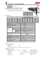
Testing conditions
* Materials : Concrete with compressive
strength, 350Kg/cm2
* Pressure added to the products : 80 N
Numbers in chart below are relative values when setting the capacity of competitor A's model A as 100.
80 N
Concrete with
compressive strength
350Kg/cm2
Comparison in hammer drilling
* Working mode : Rotary hammer
Bit diameter : 6.5mm
Competitor A
Model A
Competitor A
Model A
MAKITA
HR2400
MAKITA
HR2440
MAKITA
HR2450F
Bit diameter : 8.5mm
Comparison in drilling
0
50
100
100
100
110
110
100
150
MAKITA
HR2400
MAKITA
HR2440
MAKITA
HR2450F
Competitor A
Model A
MAKITA
HR2400
MAKITA
HR2440
MAKITA
HR2450F
Competitor A
Model A
MAKITA
HR2400
MAKITA
HR2440
MAKITA
HR2450F
0
50
100
150
Bit diameter : 12.5mm
0
50
100
150
105
105
85
80
105
105
70
100
Bit diameter : 32.0 mm
0
50
100
150
Testing conditions
* Materials : Douglas fir (Wood) of 60mm (2-3/8") in thickness
* Working mode : Drill
110
110
110


