background image

R

epair

P 13 / 18

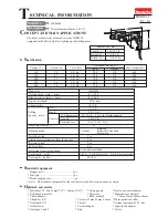
6. Reassemble swash bearing section temporarily to gear housing, and hold gear housing as illustrated in Fig. 8H. 
    So, swash bearing section tilts in the direction of arrow.
    Keeping the illustrated position, disassemble swash bearing section by striking the edge of gear housing 
    with plastic hammer. So, ball bearing 606ZZ can be removed together with swash bearing section.

7. Swash bearing section can not be disassembled in one action by pressing cam shaft with arbor press, because
    retaining ring S-7 is assembled between ball bearing 608ZZ and compression spring 7.
    Take the following steps for disassembling them.
       1. Disassemble ring 8 by pressing with arbor press as illustrated in Fig. 9.
       2. Disassemble ball bearing 608ZZ with bearing extractor as illustrated in Fig. 9A.
       3. Disassemble flat washer 8 and bearing retainer as illustrated in Fig. 9B.
       4. Disassemble helical gear 26 by pressing with arbor press as illustrated in Fig. 9C.
 

Fig. 8H

1R022 Bearing 
            extractor plate

1R023 Bearing 
            extractor ring

Ring 8

Ring 8

1R236 Round bar 
            for arbor

1R236 Round bar 
            for arbor

Ball bearing 
608ZZ

Flat washer 8

Bearing retainer

Helical 
gear 26

Swash 
bearing 10

Clutch cam

Ball bearing 
606ZZ

Retaining ring S-7

Compression 
spring 7

Spur gear 10

Cam shaft

Fig. 9

Fig. 9A

Fig. 9B

Fig. 9C

Fig. 9D

Fig. 9E

Fig. 9F

5. Disassemble swash bearing 10 and clutch cam as illustrated in Fig. 9D. And disassemble ball bearing 606ZZ
    with bearing extractor as illustrated in Fig. 9D.
6. Disassemble retaining ring S-7 with retaining ring plier as illustrated in Fig. 9E.
7. Separated compression spring 7 and spur gear 10 from cam shaft as illustrated in Fig. 9F.

Summary of Contents for HR2450F

Page 1: ...pe of bit shank Drilling capacity mm Steel Wood Concrete TCT hammer bit Core bit Dry Diamond core Single blow energy J Working mode Variable switch Reverse switch Clutch for protecting user from lock...

Page 2: ...alm fitting soft grip Change lever for 3 mode settings Rotation only Rotation Percussion Percussion only Lock button on change lever for firmly holding the position of selected mode In line and ergono...

Page 3: ...8 13 1 2 32 1 1 4 360 14 1 8 72 2 13 16 212 8 2 4 5 3 SDS plus Yes Yes Yes Yes Yes No No No 9 101 101 by double insulation HR2450 HR2450F A 780 2 7 4 0 13 1 2 Modes R R P 0 1 100 0 4 500 24 15 16 54 2...

Page 4: ...meter 6 5mm Competitor A Model A Competitor A Model A MAKITA HR2400 MAKITA HR2440 MAKITA HR2450F Bit diameter 8 5mm Comparison in drilling 0 50 100 100 100 110 110 100 150 MAKITA HR2400 MAKITA HR2440...

Page 5: ...cylinder The portion where contacts inner housing Inner portion where contacts striker The portion where piston joint is assembled Inner portion where contacts tool holder The groove where O ring 68...

Page 6: ...assemble cap 35 by turning See Fig 1 Chuck cover Ring 21 3 Take off steel ball 7 0 with which guide washer and conical compression spring 21 29 are held See Fig 1A Then guide washer and conical compr...

Page 7: ...to the original position of change lever by pressing to gear housing side 4 Disassembling change lever 1 Separate cap from change lever See Fig 1 2 Fully turn change lever in the direction of drill mo...

Page 8: ...5 4 pcs Brush holder Brush holder Gear housing Motor housing Gear housing Inner housing Plastic hammer No 1R269 Bearing extractor small Ball bearing Armature 7 Disassembling tool holder section 1 Disa...

Page 9: ...g 31 Washer 30 Round bars for arbor Ring spring 28 Retaining ring plier Retaining ring plier No 1R306 Ring spring extractor 8 Assembling tool holder section 1 Apply grease to spur gear 51 and tool hol...

Page 10: ...ring 28 showing its cut portion Ring spring Push the cut portion to the out side of the hole Push out ring spring 28 from the inner groove O ring case O ring case Fig 6 Fig 6A Inner housing side Inner...

Page 11: ...6C Fig 6D Ring spring 28 Fig 6E O ring case equipped with O ring 9 O ring 15 Ring 9 Impact bolt equipped with O ring 12 10 Assembling impact bolt 1 Apply grease to the O rings referring to 1 Lubricat...

Page 12: ...earing section Swash bearing section Fat washer 5 Compression spring 6 Stop ring E 4 Pin of inner housing Piston cylinder 3 Disassemble stop ring E 4 flat washer 5 and compression spring 6 with which...

Page 13: ...ball bearing 608ZZ with bearing extractor as illustrated in Fig 9A 3 Disassemble flat washer 8 and bearing retainer as illustrated in Fig 9B 4 Disassemble helical gear 26 by pressing with arbor press...

Page 14: ...all bearing 608ZZ Bearing retainer Ring 8 1 Apply MAKITA grease to piston cylinder and swash bearing 10 referring to 1 Lubrication at page 5 2 Assemble 2 pcs of flat washers 12 and piston joint to pis...

Page 15: ...shaft as illustrated in Fig 11E 8 Assemble compression spring 7 to cam shaft and fix the parts on cam shaft with retaining ring S 7 as illustrated in Fig 11F 9 Assemble compression spring 6 and flat w...

Page 16: ...ssor power supply cord etc can be replaced No 1R165 Ring spring setting tool B Needle bearing complete Gear housing Note in assembling Pay attention to the assembling position of needle bearing comple...

Page 17: ...See through 1 2 3 4 1 2 C1 C2 M1 M2 Switch Field Noise suppressor Power supply cord Brush holder Brush holder Connected to field ore For some countries noise suppressor of two lead wire type is used o...

Page 18: ...s lead wire blue between brush holder and lead holder Fix field brush holder s lead wire blue and field lead wire black with lead holder as per the illustration Fix lead wires which are passed throug...

Reviews: