background image

P 2 / 18 

F

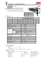
eatures and benefits

Cord guard is not
only tough but also
very flexible to
protect cable from
disconnection.

Accepting SDS-plus shank bit

Slide lock type chuck
for rapid changing bits

HR2450F

Built-in torque limiter

Palm fitting 
soft grip

Change lever for 
3 mode settings 

Rotation only 

Ro Percussion

Percussion only

Lock button on change lever for 
firmly holding  the position of 
selected mode 

In-line and ergonomical designed 
palm fitting soft grip 

Equipped with
reverse switch

Lock ON button

Practical positioning chisel angle
desired 40 positions without using
chisel adapter

LED job-light for lighting up
your working point in shadow

Summary of Contents for HR2450F

Page 1: ...pe of bit shank Drilling capacity mm Steel Wood Concrete TCT hammer bit Core bit Dry Diamond core Single blow energy J Working mode Variable switch Reverse switch Clutch for protecting user from lock...

Page 2: ...alm fitting soft grip Change lever for 3 mode settings Rotation only Rotation Percussion Percussion only Lock button on change lever for firmly holding the position of selected mode In line and ergono...

Page 3: ...8 13 1 2 32 1 1 4 360 14 1 8 72 2 13 16 212 8 2 4 5 3 SDS plus Yes Yes Yes Yes Yes No No No 9 101 101 by double insulation HR2450 HR2450F A 780 2 7 4 0 13 1 2 Modes R R P 0 1 100 0 4 500 24 15 16 54 2...

Page 4: ...meter 6 5mm Competitor A Model A Competitor A Model A MAKITA HR2400 MAKITA HR2440 MAKITA HR2450F Bit diameter 8 5mm Comparison in drilling 0 50 100 100 100 110 110 100 150 MAKITA HR2400 MAKITA HR2440...

Page 5: ...cylinder The portion where contacts inner housing Inner portion where contacts striker The portion where piston joint is assembled Inner portion where contacts tool holder The groove where O ring 68...

Page 6: ...assemble cap 35 by turning See Fig 1 Chuck cover Ring 21 3 Take off steel ball 7 0 with which guide washer and conical compression spring 21 29 are held See Fig 1A Then guide washer and conical compr...

Page 7: ...to the original position of change lever by pressing to gear housing side 4 Disassembling change lever 1 Separate cap from change lever See Fig 1 2 Fully turn change lever in the direction of drill mo...

Page 8: ...5 4 pcs Brush holder Brush holder Gear housing Motor housing Gear housing Inner housing Plastic hammer No 1R269 Bearing extractor small Ball bearing Armature 7 Disassembling tool holder section 1 Disa...

Page 9: ...g 31 Washer 30 Round bars for arbor Ring spring 28 Retaining ring plier Retaining ring plier No 1R306 Ring spring extractor 8 Assembling tool holder section 1 Apply grease to spur gear 51 and tool hol...

Page 10: ...ring 28 showing its cut portion Ring spring Push the cut portion to the out side of the hole Push out ring spring 28 from the inner groove O ring case O ring case Fig 6 Fig 6A Inner housing side Inner...

Page 11: ...6C Fig 6D Ring spring 28 Fig 6E O ring case equipped with O ring 9 O ring 15 Ring 9 Impact bolt equipped with O ring 12 10 Assembling impact bolt 1 Apply grease to the O rings referring to 1 Lubricat...

Page 12: ...earing section Swash bearing section Fat washer 5 Compression spring 6 Stop ring E 4 Pin of inner housing Piston cylinder 3 Disassemble stop ring E 4 flat washer 5 and compression spring 6 with which...

Page 13: ...ball bearing 608ZZ with bearing extractor as illustrated in Fig 9A 3 Disassemble flat washer 8 and bearing retainer as illustrated in Fig 9B 4 Disassemble helical gear 26 by pressing with arbor press...

Page 14: ...all bearing 608ZZ Bearing retainer Ring 8 1 Apply MAKITA grease to piston cylinder and swash bearing 10 referring to 1 Lubrication at page 5 2 Assemble 2 pcs of flat washers 12 and piston joint to pis...

Page 15: ...shaft as illustrated in Fig 11E 8 Assemble compression spring 7 to cam shaft and fix the parts on cam shaft with retaining ring S 7 as illustrated in Fig 11F 9 Assemble compression spring 6 and flat w...

Page 16: ...ssor power supply cord etc can be replaced No 1R165 Ring spring setting tool B Needle bearing complete Gear housing Note in assembling Pay attention to the assembling position of needle bearing comple...

Page 17: ...See through 1 2 3 4 1 2 C1 C2 M1 M2 Switch Field Noise suppressor Power supply cord Brush holder Brush holder Connected to field ore For some countries noise suppressor of two lead wire type is used o...

Page 18: ...s lead wire blue between brush holder and lead holder Fix field brush holder s lead wire blue and field lead wire black with lead holder as per the illustration Fix lead wires which are passed throug...

Reviews: