
P
9
/ 1
7
R
epair
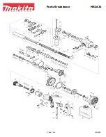
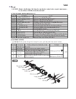
[3] ASSEMBLY/ DISASSEMBLY
[3]-4. Crank section
DISASSEMBLING
(1) Remove Handle section. (
Fig. 2
)
(2) Remove Housing cover and Barrel section. (
Fig.
8) No need to disassemble Chuck section.
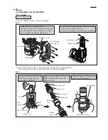
(3) Remove Active dynamic vibration absorber from Crank housing exclusively for HM1213C. (
Figs. 14 and 15)
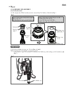
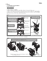
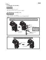
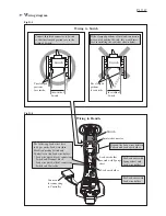
(4) Remove Rear cover and disconnect Carbon brushes from the commutator of Armature as illustrated in
Fig. 19
.
Note
: This is a necessary step to remove Armature from machine.
Carbon brush is pressed with
Spiral spring to maintain its
contact with commutator of
Armature.
Carbon brush
Spiral spring
Carbon brush
Carbon brush
Spiral spring
Armature shaft of
commutator end
Armature shaft of
commutator end
Armature shaft of
commutator end
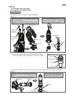
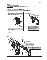
Remove six M6x40 Hex socket button head screws.
Separate Motor housing from Crank housing by levering up Crank housing with 1R263.
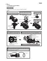
Detach Spiral spring
from Carbon brush.
Disconnect from commutator
of Armature by pulling
Carbon brush,.
Disassemble Rear cover from
Motor housing as follows.
Rear cover
5x25 Tapping screw (3pcs.)
Motor housing
Fig. 19
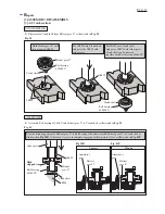
Fig. 20
1R263
Motor housing
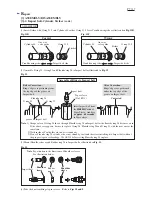
Note
: Flat washer 15 may come out with Armature at this time.
Pay attention not to lose it.
(5) Separate Motor housing from Crank section as illustrated in
Fig. 20
.
Flat
washer 15