P 1
1
/ 1
7
R
epair
[3] ASSEMBLY/ DISASSEMBLY
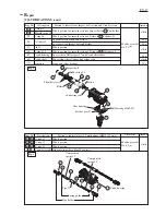
[3]-4. Crank section
DISASSEMBLING
ASSEMBLING
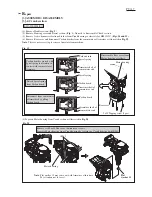
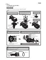
(7) Disassemble Crank shaft from Helical gear 57 as illustrated in Fig. 24.
Crank shaft
Ball bearing
6206LLU
Helical gear 57
Hold Helical gear 57 with
two pieces of 1R258.
Put 1R029 onto Crank shaft,
and press the 1R029 with
Arbor press.
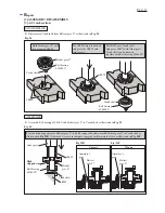
Put 1R029 onto Crank shaft.
And press 1R029 with Arbor press.
Crank shaft can be removed
together with Ball bearing 6206LLU.
1R029
(1) Assemble Ball bearing 6206LLU and Helical gear 57 to Crank shaft as illustrated in Fig. 25.
Ball bearing
6206LLU
Crank shaft
Fig. 24
Correct
1R258
1R029
Arbor press
Helical
gear 57
Helical
gear 57
Crank shaft
Face the high stepped rim of Helical gear 57 to Ball bearing side, and assemble Helical gear 57 to Crank shaft as
illustrated in Fig. 23R. Otherwise, it causes incomplete engaging with Armature’s Gear as illustrated in Fig. 23F.
Wrong
High
stepped rim
Ball bearing
6206LLU
Armature’s
gear
Armature’s
gear
Helical
gear 57
Fig. 25
Fig. 23R
Fig. 23F
1R258


