


Model No.
Description
PRODUCT
C
ONCEPT AND MAIN APPLICATIONS
S
pecification
Dimensions: mm (")
Width (W)
Height (H)
Length (L) 356 (14)
380 (15)
77 (3)
HR2300 HR2310T
209 (8-1/4)
HR2300
HR2310T
Rotary Hammer 23mm (7/8")
Combination Hammer 23mm (7/8")
HR2300 is a 23mm (7/8") 2-mode rotary hammer while HR2310T is
a 23mm (7/8") 3-mode combination hammer with quick change drill chuck.
Both models are adapted for SDS-PLUS bits, featuring compact and
lightweight design, enhanced comfort and better control with ergonomic handle.
HR2300 series models are available in the variations listed below, including
HR2600 and HR2610 series models developed on the same concept.
For information of HR2600 and HR2610 series models,
see “
TECHNICAL INFORMATION
” of each series.
P 1/ 23
Chuck type
HR2300
HR2310T
Yes (by trigger)
Yes
Europe, North America: 4.0 (13.1), Australia, Brazil: 2.0 (6.6),
Other countries: 2.5 (8.2)
Yes
0 - 1,200
0 - 4,600
Adapted for
SDS-PLUS shank bits
Adapted for SDS-PLUS shank bits
and Round shank bits
*1
23 (7/8)
68 (2-11/16)
2.9 (6.3)
Impacts per minute= minֿ¹
No load speed: minֿ¹= rpm
Specification
Double insulation
Power supply cord: m (ft)
Variable speed control
Rotation reversing facility
2.7 (5.9)
Operation mode
2 modes
(Rotation only/ Rotation with Hammering)
3 modes
(Rotation only/ Rotation with Hammering/
Hammering only)
Model
*1
Round shank bits can also be used by replacing the factory-mounted chuck with Quick change drill chuck (keyless).
*2
with side grip
Concrete
TCT bit
Steel
Wood
Core bit
Diamond core bit
Capacities:
mm (")
Continuous Rating (W)
Voltage (V)
Cycle (Hz)
Input
Output
Max. Output (W)
110
120
220
230
240
6.9
6.2
3.4
3.3
3.2
50/ 60
50/ 60
50/ 60
50/ 60
50/ 60
720
---
720
720
720
300
300
300
300
300
500
500
500
500
500
127
6.0
50/ 60
720
300
500
Current (A)
70 (2-3/4)
13 (1/2)
32 (1-1/4)
Yes
Torque limiter
Model
Operation Mode
LED
Chuck type
2 modes
(Rotation only/
Rotation with hammering)
3 modes
(Rotation only/
Rotation with hammering/
Hammering only)
No
No
26mm
Capacity
23mm
23mm
26mm
No
No
Adapted for
SDS-PLUS shank bits
Adapted for
SDS-PLUS shank bits
and Round shank bits
*
Yes
No
AVT
No
No
No
Yes
Yes
No
No
Yes
Yes
No
HR2300
HR2310T
HR2610T
HR2611FT
HR2600
HR2601
HR2611F
HR2610
*
Round shank bits can also be used by
replacing the factory-mounted chuck with
Quick change drill chuck
(keyless).
T
ECHNICAL INFORMATION
H
W
L
Weight according to
EPTA-Procedure 01/2003
*2
: kg (lbs)
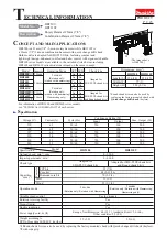
(The image above
is HR2300.)