background image

R

epair

P  7/ 23

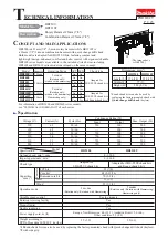
Apply the following grease/ lubricant to protect parts and product from unusual abrasion.

[2] LUBRICATION

 (for HR2300)

Fig. 1

Item No.

Description

Grease/ Lubricant Amount

Portion to lubricate

Makita grease RB No. 00

Makita lubricating oil VG100

Makita lubricating

oil VG100

Makita grease RB

No. 00

26

1

Cap 35

Gear housing complete Oil seal 25 on the inside of Gear housing complete

Lip portion where Bit is to be inserted

Entire surface

Entire surface

Entire surface

(h) Ball bearing portion

(g) Interleaved portion to Piston joint 

Entire surface
Gear portion

2g

3g
3g

3g

19g

in total

29

Steel ball 7.0 (2 pcs.)

Whole portion

(c)

(d)

(a)

(b)

(e)

(f)

(g)

(h)

Portion that contacts Sleeve 9  

32

28

a little

a little

a little

a little

42

44
45

46

47

56

58

64

65

70
71

30

Driving flange

O ring 9

Tool holder complete

HR2300

20
21
23

26

28

29

30

38

42

36

Pin 6

Piston 

joint

44

45

46

47

56

58

64

65

70

1

71

37

32

30

Portion that contacts        Spur gear 51/ Pins 6

30

Portion that contacts        Spur gear 51/ Pins 6

16

(e) Gear portion

(f) Portion that contacts  58  Swash bearing 10

Gear portion that engages with Armature gear shaft

Inside that contacts  48  Piston joint    

38

Impact bolt

Entire surface

37

Sleeve 9A

Entire surface

(b) Inside where  46  Piston cylinder reciprocates

16
20

21

Push corn

Portion that contacts Clutch cam B

Compression spring 5

Periphery

23

O ring 21

Striker
O ring 17.5

Piston cylinder

(c) Inside where  44  Striker moves
(d) Periphery that  28  Tool holder complete contacts 

Guide plate

Spur gear 10

Clutch cam B

Swash bearing 10

Helical gear 26

O-ring 68

O ring 26
Oil seal 12

Flat washer 30

36

Portion that contacts  Inner housing complete

Flat washer 30

Spur gear 51

(a) Periphery that contacts Driving flange / Spur gear 51

Summary of Contents for HR2300

Page 1: ...supply cord m ft Variable speed control Rotation reversing facility 2 7 5 9 Operation mode 2 modes Rotation only Rotation with Hammering 3 modes Rotation only Rotation with Hammering Hammering only M...

Page 2: ...er drill bits Taper shank TCT hammer drill bits Taper shank adaptor Cotter Core bits Center bits Core bit adaptor Rod Drill chuck ass y Chuck adapter assembly Drill chuck S13 Chuck key S13 Tool holder...

Page 3: ...rent models Easy depth adjustment Depth gauge can be adjusted with a single motion Rubberized soft grip provides enhanced comfort and control Plastic carrying case Large carrying handle Large latches...

Page 4: ...st diameter 16 5mm 5 8 0 50 100 150 115 slow fast Note 1 The test results depend to a great extent on the hardness of materials etc 2 Numbers in the chart below are relative values when the capacities...

Page 5: ...5 0 3 TE2 Makita BOSCH HITACHI HILTI Yes Yes 4 0 13 1 650 No unknown 0 1 200 0 4 600 22 7 8 13 1 2 20 13 16 unknown 352 13 7 8 89 3 1 2 203 8 Width Length Model unknown 90 89 3 16 16 0 3 GBH2 23RE GBH...

Page 6: ...ving Helical gear 26 for HR2310T Bearing setting plate 12 2 1R034 Tip for retaining ring pliers 1R212 Use with 1R003 1 4 Hex shank bit for M4 1R228 removing M4 Hex socket head bolt Ring spring setting...

Page 7: ...Driving flange O ring 9 Tool holder complete HR2300 20 21 23 26 28 29 30 38 42 36 Pin 6 Piston joint 44 45 46 47 56 58 64 65 70 1 71 37 32 30 Portion that contacts Spur gear 51 Pins 6 30 Portion that...

Page 8: ...ng flange O ring 9 Tool holder guide complete HR2310T Sleeve 9 29 30 Pin 6 32 36 30 Portion that contacts Spur gear 51 Pins 6 6 pcs 30 Portion that contacts Spur gear 51 Pins 6 6 pcs Portion that cont...

Page 9: ...nd Tool holder complete Chuck cover is removed 4 Remove two Steel balls 7 0 while pressing down Ring 21 Fig 5 Ring 21 Guide washer and Conical compression spring 21 29 are removed Fig 3 Fig 4 Fig 6 Fi...

Page 10: ...with 1R004 from Tool holder guide complete side Flat washer 24 Leaf spring and Steel ball 5 are removed Fig 11 5 Remove two Steel balls 6 Torsion spring 31and Change ring from Tool holder Fig 12 Fig...

Page 11: ...a 4 Put Steel ball 5 0 in the groove surrounded by Change cover and Tool holder left in Fig 16 5 Set Leaf spring and Flat washer 24 in change cover then secure them with Ring spring 21 right in Fig 16...

Page 12: ...Leaf spring and Steel ball 5 0 can be removed Pull off Change cover Change ring and Torsion spring 31 can be removed Torsion spring 31 Chuck holder Spacer Chuck holder Chuck holder Chuck holder Space...

Page 13: ...5 Mount Steel ball 5 Leaf spring and Flat washer 24 to Chuck holder then secure them with Ring spring 21 Fig 25 Spacer Spacer Spacer Insert the short arm of Torsion spring 31 into the hole of Chuck h...

Page 14: ...B on Change lever B Note The V groove of Change lever B has to come on the center of Leaf spring Fig 28 4 Be sure to check Change lever B works properly after assembling 1 Set Change lever A to hammer...

Page 15: ...r section HR2310T 2 Remove Change lever section 3 Separate Gear housing from Motor housing 4 Remove Tool holder complete HR2300 Tool holder guide complete HR2310T by tapping the top as drawn in Fig 33...

Page 16: ...ely to push it out of the inner groove of Tool holder guide complete 4 The components are removed by tapping with Phillips screwdriver and plastic hammer from bit installation side of Tool holder guid...

Page 17: ...drawn in Fig 41 Note Do not reuse the removed Ring spring 28 if it is deformed or damaged Piston cylinder as a jig Piston cylinder as a jig Tool holder guide complete end gap hole Inner groove of Tool...

Page 18: ...zontally with Swash bearing 10 kept tilted and remove the pole of Swash bearing 10 toward the tilted direction Swash bearing section Note Ball bearing 606ZZ is left in Gear housing complete Swash bear...

Page 19: ...ression spring 14 on the boss of Inner housing complete Fig 47 3 Put the opposite end of Compression spring 14 on Guide plate then push Piston cylinder into the bottom of Inner housing complete and in...

Page 20: ...n spring 4 on Lock plate mating side in order to do the next step smoothly 3 While holding Lock plate by a finger so as not to drop from the guide of Gear housing complete Assemble Gear housing comple...

Page 21: ...plete on 1R258 as drawn in Fig 53 pressfit Oil seal 25 with 1R232 until it stops Fig 54 Oil seal 25 is not yet inserted completely because the outer diameter of 1R232 is larger than that of Oil seal s...

Page 22: ...57 HR2300 HR2310T Cap 35 286288 8 6 Ring spring 14 233989 9 1 Cap 35 286263 4 105 Ring spring 15 233992 0 105 Rubber washer 16 424364 2 107 O ring 9 213073 6 42 40 Cushion ring 12 424267 0 26 Steel b...

Page 23: ...cord Strain relief Switch Fix white lead wire in this lead wire holder Fix black lead wire in this lead wire holder Lead wires black white must be tight between Brush holder unit and Lead wire holder...

Reviews: