background image

Repair Manual EA6100P / EA6101P

25

11  CYLINDER / PISTON

1

2

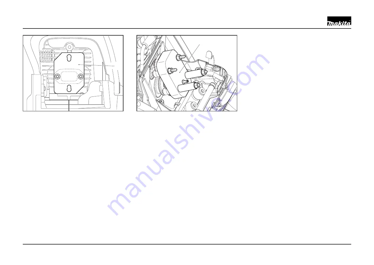
Drive, pressure test

If it is not possible to adjust the carburetor 
properly, it will be necessary to check the 
sealing of the Drive.

To seal the exhaust side, install sealing plate 

1

 (944.603.180) in the place of the muf

 er 

(rubber coating towards the cylinder). 
To do this it will be necessary to remove the 
muf

 er, see chap. 04.

To seal the intake side, install sealing plate 

2


(944.603.200) in the place of the carburetor 
unit. 
To do this it will be necessary to remove the 
carburetor unit, see chap. 07 and 08.
Connect the over/underpressure pump 
to the connection on the sealing plate 

2


(944.603.200)

Move the piston to top dead centre.
Pull the pulse line from the cylinder connection 
and seal the connection.
Set up a pressure of max. 0.5 bar.
If the pressure drops within 20 seconds, it can 
have one of these causes:
•• Radial ring leaking
•• Cylinder base gasket leaking
•• Crankcase gasket leaking
•• Crack in crankcase
•• Crack in cylinder
•• Spark plug leaking

NOTE:

 Detergent can be used to localise 

leaks. If there is a leak into the oil tank, it 
will not be possible to fully identify the leak. 
If pressure remains steady in the crankcase 
after shutting off the oil line hole, for example 
with a rubber stopper (see chap. 05), it is 

an indication that there is a defect in the 
crankcase gasket to the oil tank.

Drive, vacuum test

Since the radial gasket ring can also fail 
at negative pressure, a vacuum must be 
established in the crankcase to test the radial 
ring.
Seal off the intake and exhaust sides as 
described above.
Connect the over/underpressure pump to the 
connection on the sealing plate 

2

.

Move the piston to top dead centre.
Pull the pulse line from the cylinder connection 
and seal the connection.
Set up a negative pressure of max. 0.5 bar.
If the pressure does not rise to more than 
0.3 bar within 20 seconds, the radial gasket 
is OK. Otherwise the radial gaskets must be 
replaced.
Remove the 

 ywheel and clutch, see 

IGNITION SYSTEM

 and 

CLUTCH / CLUTCH 

DRUM

.

On the clutch side, pull the circlip from the 
shaft.
Guide the 15 mm radial gasket puller 
(944.500.895) over the shaft and turn it 

 rmly 

into the radial gasket. When the spindle is 
screwed in, it will press against the shaft and 
pull the radial gasket out.

Caution: Under no circumstances hammer 
in the puller.

Summary of Contents for EA6100P

Page 1: ...l EA6100P EA6101P Caution Before doing any maintenance or service work the combination switch must be in STOP position ignition current interrupted in order to prevent unintended starting by the easy...

Page 2: ...ng 14 Spark plug 15 Checking the ignition spark 16 Checking the ignition 16 Replacing the plug connector 16 Removing the ywheel 17 Starting ratchets 17 Removing the ignition armature 18 Installing the...

Page 3: ...per ISO 7293 kg h 1 5 Speci c consumption at max load per ISO 7293 g kWh 430 Fuel tank capacity l 0 8 Chain oil tank capacity l 0 48 Mixture ratio fuel two stroke oil when using MAKITA oil 50 1 100 1...

Page 4: ...en ywheel and armature 944 500 891 4 Torque wrench 3 8 Drive socket 944 500 864 Bit 152 mm 944 500 865 Bit 49 mm 944 500 866 Torque wrench 3 8 Drive 950 230 000 5 Piston stop wedge Wedge for blocking...

Page 5: ...disassembly tasks 944 603 400 10 Over underpressure pump For checking sealing of radial rings carburetor 957 004 001 11 Sealing plate For sealing intake side 944 603 200 12 Sealing plate For sealing...

Page 6: ...function An angled worm drive converts the turns of the adjustment screw 1 to forward or backward motion of the tensioning pin 2 If necessary turn adjusting screw 1 clockwise until the fastening scre...

Page 7: ...the chain sprocket A worn chain sprocket will damage a new saw chain and must be replaced Check the clutch drum needle bearing for wear and damage Assembly the bearing with multi purpose high perform...

Page 8: ...drum see chapter 02 Push the hand guard forward to engage the chain brake This releases the brake band spring Remove the cover plate see chapter 01 Fold the brake band 1 upward and turn it out of the...

Page 9: ...ssary push it back into position with a screwdriver about 5 mm from the axle support The handguard can only be assembled when the rest piece is in this position Assemble the handguard and disengagemen...

Page 10: ...on If a catalytic converter is being used the muf er will be very hot after operation Move piston to bottom dead centre visible through the exhaust opening Press the piston stop wedge 3 cap 00 pos 5 i...

Page 11: ...position of the springs Do not replace springs individually If a spring breaks or is fatigued all three springs must be replaced The springs must not touch the cover The illustration shows the inside...

Page 12: ...from the oil pump Unsrew screw 4 and remove the oil pump Remove spacer ring 5 from the crankshaft Note Make sure to install in the right position See illustration The suction line 6 remains in the cr...

Page 13: ...s shown in the schematic Assembly Note If installing a new return spring cassette grease it on the spring side Carefully insert a new return spring cassette 6 and press down until it engages Lightly g...

Page 14: ...ective air filter check carburetor adjustment Use MAKITA EXTRA two stroke oil Adjust spark gap Wash spark plug in acetone Do not sandblast If necessary replace spark plug Eliminate cause wrong carbure...

Page 15: ...ves The spark plug NGK BPMR 7A parts no 965 603 021 must be replaced in case of damage to the insulator electrode erosion burn or if the electrodes are very dirty or oily Pull the plug cap 3 off the s...

Page 16: ...t off For ignition cut offs see IGNITION SYSTEM TROUBLE SHOOTING Replacing the plug connector Hold the plug connector spring using pointed pliers and push the rubber cap backwards over the ignition ca...

Page 17: ...f the shaft Do not screw the mandrel all the way down Leave about 2 mm between the mandrel and the ywheel Hold the machine in one hand and knock the ywheel loose with a tap on the mandrel CAUTION The...

Page 18: ...grommet into the carburettor when doing this If the grommet gets pushed out it can be reinserted from the cylinder side Route the high voltage cable as shown engage the cooling air guide tab 5 and sec...

Page 19: ...ngage the air ap linkage 6 from the carburetor Assembly Place the insert 5 in the intake manifold if necessary Engage the air ap linkage 6 see illustration Note Engage the air ap linkage 6 on the carb...

Page 20: ...ase Assembly Assemble in reverse order Route the lines as shown Tighten bolts 8 to 5 0 5 Nm Removing the manifold ange Unscrew 4 bolts 13 and remove the manifold ange 1 Pulse line 2 Fuel line red 4 Pr...

Page 21: ...d it needs to be replaced along with the gasket 19 Check Screen 22 for contamination Pulse hole for contamination Check control parts control lever inlet needle Check the tip of the inlet needle for w...

Page 22: ...lutch side over damper springs B and C spread the engine unit slightly apart from the tank Unscrew the damper springs Damper spring D Note Damper spring D cannot be removed until damper springs A B an...

Page 23: ...bricate the Bowden cable The grip shell is attached to the tank with a Torx screw 3 Disengage the throttle lock 1 and spring 2 Check for ease of motion and functioning of the safety throttle lock spri...

Page 24: ...eck the following Air valve Fuel line Tank cap O ring Check tank for holes Note Detergent can be used to localise leaks Vacuum testing ventilation valve 9 Attach the over underpressure pump as describ...

Page 25: ...is a leak into the oil tank it will not be possible to fully identify the leak If pressure remains steady in the crankcase after shutting off the oil line hole for example with a rubber stopper see c...

Page 26: ...ly lightly oil the cylinder race piston and needle bearing 6 Install the piston with the arrow marking 4 on the outlet side of the camshaft piston ring lock on the inlet side Move piston to bottom dea...

Page 27: ...driving the crankshaft into the crankcase MS or CS support the crankshaft side between the webs When installing the second crankcase half the crankshaft webs must be supported against each other NOTE...

Page 28: ...5 205 Torx 2 5 0 5 ywheel fastening by nut 920 308 024 A F 13 1 28 2 0 starter cpl to crank case 908 005 205 Torx 3 5 0 5 handguard mounting to starter housing 908 005 205 Torx 1 5 0 5 grip half rear...

Page 29: ...Repair Manual EA6100P EA6101P 29 NOTES...

Page 30: ...MAKITA Werkzeug GmbH Postfach 70 04 20 D 22004 Hamburg Germany...

Reviews: