13
ENGLISH
NOTE:
The lamp for mode 1 blinks in green if the
machine is operated under unoperatable conditions.
The lamp blinks in one of the following conditions.
•
The switch trigger is pulled, when the bolt on the
fan cover or suction pipe is not tightened firmly,
or the bolt on the blower pipe or elbow pipe is
not tightened firmly.
•
The machine is turned on, when the control
lever is not fully returned to the off position, or
while you are pulling the switch trigger.
NOTE:
This machine employs the auto power-off
function. To avoid unintentional start up, the main
power switch will automatically shut down when the
switch trigger is not pulled for a certain period after
the main power switch is turned on.
Switch action
WARNING:
Before installing the battery car
-
tridge into the machine, always check to see that
the switch trigger actuates properly and returns
to the "OFF" position when released.
►
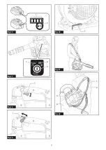
Fig.18:
1.
Switch trigger
To start the machine, simply pull the switch trigger. The
speed is increased by increasing pressure on the switch
trigger. Release the switch trigger to stop.
Cruise control function
The cruise control function allows the operator to main-
tain a constant speed without pulling the trigger. To
increase the speed, turn the control lever forward. To
decrease the speed, turn the control lever backward.
►
Fig.19:
1.
Control lever
Hex wrench storage
When not in use, store the hex wrench as illustrated to
keep it from being lost.
►
Fig.20:
1.
Hex wrench
Accidental re-start preventive
function
If you turn on the machine while pulling the switch trig-
ger or while the control lever is not in the off position,
the machine does not start. To start the machine, first
release the switch trigger and return the control lever
fully, and then turn on the machine.
Electronic function
The machine is equipped with the electronic function for
easy operation.
•
Constant speed control
The speed control function provides the constant
rotation speed regardless of load conditions.
OPERATION
CAUTION:
Do not place the machine on the
ground while it is switched on.
Sand or dust may
enter from suction inlet and cause a malfunction or
personal injury.
Blower operation
CAUTION:
When performing the blower
operation, be sure to remove the suction pipe,
suction nozzle, elbow pipe and dust bag from the
machine, and attach the blower pipe and nozzles
to the machine.
Hold the machine firmly with a hand and perform the
blowing operation by moving it around slowly. When
blowing around building, big stone or vehicle, direct the
nozzle away from them. When performing an operation
in a corner, start from the corner and then move to wide
area.
►
Fig.21
Vacuuming operation
CAUTION:
When performing the vacuuming
operation, be sure to remove the blower pipe and
nozzles from the machine, and attach the suction
pipe, suction nozzle, elbow pipe, dust bag, and
shoulder strap to the machine.
CAUTION:
Check the dust bag frequently for
wear or deterioration.
CAUTION:
Be sure to fasten the fastener of
the dust bag before operating the machine.
CAUTION:
Always switch off the machine
before opening or fastening the fastener of the
dust bag.
NOTICE:
Do not allow wet materials, such as
wet leaves, and foreign materials, such as large
wood chips, metals, glass, pebbles, etc., to be
sucked into the machine.
Otherwise, a malfunction
may occur.
NOTICE:
Empty the dust bag before it becomes
full.
Otherwise, a malfunction may occur.
NOTICE:
To prevent the suction of foreign mate
-
rials, operating the machine in the vacuuming
mode is recommended.
1.
Put the shoulder strap and dust bag on the shoul-
der as shown in the figure. Adjust the length of the
strap.
►
Fig.22:
1.
Shoulder strap
2.
Carry handle
3.
Assist
handle
4.
Dust bag
2.
Hold the carry handle with your right hand and the
assist handle with the other hand.
►
Fig.23
3.
While operating the machine, adjust the switch
trigger so that the suction force is appropriate for the
work location and conditions.
Summary of Contents for DUB363ZV
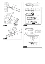
Page 2: ...1 2 1 Fig 1 1 2 Fig 2 1 2 Fig 3 1 2 3 Fig 4 2 ...
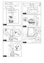
Page 3: ...2 1 3 Fig 5 1 1 Fig 6 1 Fig 7 1 2 3 3 Fig 8 1 2 3 Fig 9 1 2 3 Fig 10 3 ...
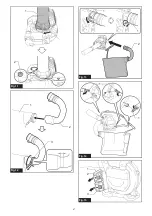
Page 4: ...1 2 Fig 11 2 3 1 Fig 12 1 2 1 Fig 13 1 1 Fig 14 1 2 3 Fig 15 4 ...
Page 5: ...1 2 Fig 16 2 1 3 Fig 17 1 Fig 18 1 Fig 19 1 Fig 20 Fig 21 1 4 3 2 Fig 22 5 ...
Page 6: ...Fig 23 1 Fig 24 6 ...
Page 75: ...75 ...


