


7
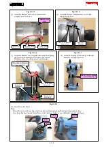
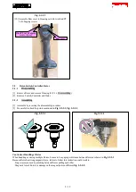
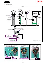
Wiring diagram
Fig. 7-1
With attention to “Points for routing Lead wires”, put the lead wires of
LED circuit between the projection of Hammer case complete and the
rib B, also between Hammer case complete and F/R Change lever.
A
A
B
B
Wiring around Hammer case complete
Projection of Hammer case complete
Hammer case complete
Boss
LED circuit
Rib A
Rib B
F/R Change lever
Cross section
of A
Projection of Hammer case complete
Hammer case
complete
Area 1
Area 2
[2] Do not put the lead wires of LED circuit on Area 1
and 2 (between the Rib C and Hammer case
complete).
[1] Do not put the lead wires of LED circuit on this area
(between the projection on Hammer case complete
and Housing).
Cross section
of B
Lead wires
Lead wires
Rib C
Put the lead wires of LED
circuit between the rib A
and the boss.
Points for routing Lead wires
15 / 19