


2
CAUTION
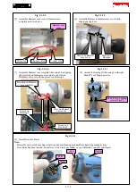
Repair the machine in accordance with “Instruction manual” or “Safety instructions”.
Follow the instructions described below in advance before repairing:
·
Wear gloves.
·
In order to avoid wrong reassembly, draw or write down where and how the parts are assembled, and what are the parts.
It is also recommended to have boxes ready to keep disassembled parts by group.
·
Handle the disassembled parts carefully. Clean and wash them properly.
3
NECESSARY REPAIRING TOOLS
Code No.
Description
Use for
1R003
Retaining ring S pliers ST-2N
removing Ring spring 11
1R016
1/4" Hex shank bit M6
removing Rotor
1R040
Armature holder 50 set for use with Vise
removing / assembling Hammer case complete
1R045
Gear extractor (large)
disassembling Hammer section
1R212-A
Tip for retaining ring pliers
use with 1R003
1R212-B
Plate set (with screws)
1R223
Torque wrench shaft 20-90N·m
assembling Hammer case complete
1R224
Ratchet head 12.7
use with 1R223
1R232
Pipe 30
removing Bit sleeve
1R263
Bearing extractor
removing Rotor
1R288
Screwdriver magnetizer
removing Steel balls
1R402-A
Digital tester
diagnosing Controller
-
Socket 30-78
use with 1R223 and Nut spinner handle in order to remove/
assemble Hammer case complete
-
Socket 32-50
removing/ assembling Hammer case complete
-
Nut spinner handle (Square drive: 12.7 mm)
removing Hammer case complete
4
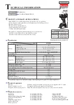
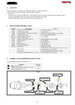
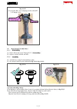
LUBRICANT AND ADHESIVE APPLICATION
Apply the following lubricants and adhesives.
Lubricant
Amount
Makita grease FA. No.2
a little
Mixture of Makita Grease FA No.2 (90%) and
Molybdenum disulfide (10%)
a little
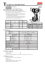
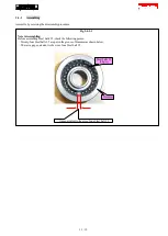
Fig. 4-1
Flat washer 24
Hole on Anvil
Contact surface
with Steel ball 3.5
Gear portion: 2g
Surface of Anvil
Inner groove on
Hammer
Drum portion on
Spindle
3 / 19