17 ENGLISH
Operation with abrasive cut-off /
diamond wheel
Optional accessory
WARNING:
When using an abrasive cut-off
/ diamond wheel, be sure to use only the special
wheel guard designed for use with cut-off wheels.
(In some European countries, when using a diamond
wheel, the ordinary guard can be used. Follow the
regulations in your country.)
WARNING:
NEVER use cut-off wheel for side grinding.
WARNING:
Do not "jam" the wheel or apply
excessive pressure. Do not attempt to make an exces
-
sive depth of cut.
Overstressing the wheel increases
the loading and susceptibility to twisting or binding of the
wheel in the cut and the possibility of kickback, wheel
breakage and overheating of the motor may occur.
WARNING:
Do not start the cutting operation
in the workpiece. Let the wheel reach full speed and
carefully enter into the cut moving the tool forward
over the workpiece surface.
The wheel may bind, walk
up or kickback if the power tool is started in the workpiece.
WARNING:
During cutting operations, never
change the angle of the wheel.
Placing side pressure
on the cut-off wheel (as in grinding) will cause the wheel
to crack and break, causing serious personal injury.
WARNING:
A diamond wheel shall be oper
-
ated perpendicular to the material being cut.
Mount the inner flange onto the spindle.
Fit the wheel / disc on the inner flange and screw the
lock nut onto the spindle.
►
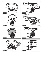
Fig.23:
1.
Lock nut
2.
Abrasive cut-off wheel / dia
-
mond wheel
3.
Inner flange
4.
Wheel guard
for abrasive cut-off wheel / diamond wheel
For Australia and New Zealand
►
Fig.24:
1.
Lock nut
2.
Outer flange 78
3.
Abrasive
cut-off wheel / diamond wheel
4.
Inner
flange 78
5.
Wheel guard for abrasive cut-
off wheel / diamond wheel
Operation with wire cup brush
Optional accessory
CAUTION:
Check operation of brush by run
-
ning tool with no load, insuring that no one is in
front of or in line with brush.
CAUTION:
Do not use brush that is damaged, or
which is out of balance.
Use of damaged brush could increase
potential for injury from contact with broken brush wires.
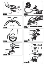
►
Fig.25:
1.
Wire cup brush
Remove the battery cartridge and place the tool upside
down allowing easy access to spindle.
Remove any accessories on spindle. Thread wire cup
brush onto spindle and tighten with supplied wrench.
NOTICE:
Avoid applying too much pressure
which causes over bending of wires when using
brush.
It may lead to premature breakage.
Operation with wire wheel brush
Optional accessory
CAUTION:
Check operation of wire wheel
brush by running tool with no load, insuring that
no one is in front of or in line with the wire wheel
brush.
CAUTION:
Do not use wire wheel brush that
is damaged, or which is out of balance.
Use of
damaged wire wheel brush could increase potential
for injury from contact with broken wires.
CAUTION:
ALWAYS use guard with wire
wheel brushes, assuring diameter of wheel fits
inside guard.
Wheel can shatter during use and
guard helps to reduce chances of personal injury.
►
Fig.26:
1.
Wire wheel brush
Remove the battery cartridge and place the tool upside
down allowing easy access to spindle.
Remove any accessories on spindle. Thread wire wheel
brush onto spindle and tighten with the wrenches.
NOTICE:
Avoid applying too much pressure
which causes over bending of wires when
using wire wheel brush.
It may lead to premature
breakage.
Operating with offset diamond
wheel
Optional accessory
With optional accessories, you can use this tool for
planing concrete surface.
WARNING:
For offset diamond wheels that
are 7 mm or thinner, place the convex section of
the lock nut upwards and attach to the spindle.
CAUTION:
Dust collecting wheel guard for the
offset diamond wheel is only for use in planing
concrete surface with a offset diamond wheel. Do
not use this guard with any other cutting acces
-
sory or for any other purpose.
CAUTION:
Before operation, make sure that
a vacuum cleaner is connected to the tool and
turned on.
Remove the battery cartridge and install the dust col
-
lecting wheel guard for the offset diamond wheel.
Mount the inner flange onto the spindle. Fit the offset
diamond wheel on the inner flange and tighten the lock
nut onto the spindle.
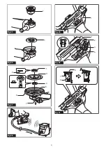
►
Fig.27:
1.
Lock nut
2.
Convex section
3.
Offset
diamond wheel
4.
Inner flange
5.
Spindle
6.
Dust collecting wheel guard for the offset
diamond wheel
7.
Shaft lock
Summary of Contents for DGA701ZU
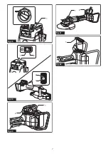
Page 2: ...1 2 3 Fig 1 1 2 Fig 2 1 Fig 3 1 Fig 4 1 2 Fig 5 1 Fig 6 Fig 7 1 2 3 Fig 8 2 ...
Page 5: ...1 Fig 25 1 Fig 26 2 1 3 4 5 6 7 Fig 27 Fig 28 1 Fig 29 4 3 1 2 Fig 30 1 2 3 Fig 31 5 ...
Page 6: ...1 Fig 32 1 2 2 1 Fig 33 Fig 34 1 Fig 35 2 1 Fig 36 1 Fig 37 6 ...
Page 7: ...1 Fig 38 1 2 2 1 Fig 39 1 2 Fig 40 2 1 Fig 41 1 Fig 42 7 ...
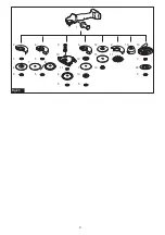
Page 8: ...1 8 2 3 5 6 3 13 2 5 4 14 15 16 17 18 12 7 5 10 6 7 19 20 3 5 11 5 8 9 Fig 43 8 ...
Page 131: ...131 ...

