14 ENGLISH
NOTE:
Depending on the conditions of use and the
ambient temperature, the indication may differ slightly
from the actual capacity.
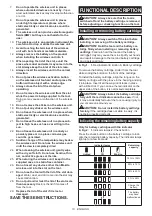
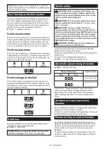
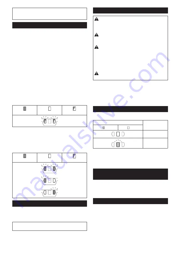
Tool / battery protection system
The tool is equipped with a tool/battery protection sys
-
tem. This system automatically cuts off power to the
motor to extend tool and battery life. The tool will auto
-
matically stop during operation if the tool or battery is
placed under one of the following conditions:
►
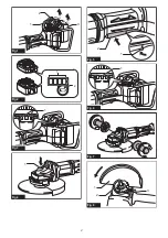
Fig.3:
1.
Battery indicator
Overload protection
When the tool is operated in a manner that causes it to
draw an abnormally high current, the tool automatically
stops without any indication. In this situation, turn the
tool off and stop the application that caused the tool to
become overloaded. Then turn the tool on to restart.
Overheat protection
When the tool or batteries is overheated, the tool stops
automatically and the battery indicators blink about 60
seconds. In this situation, let the tool and batteries cool
before turning the tool on again.
On
Off
Blinking
Overdischarge protection
When either battery's capacity becomes too low, the
tool stops automatically and the battery indicator on its
side lights up. In this case, remove the battery from the
tool and charge the battery.
On
Off
Blinking
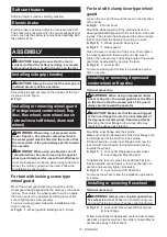
Shaft lock
Press the shaft lock to prevent spindle rotation when
installing or removing accessories.
►
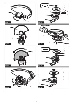
Fig.4:
1.
Shaft lock
NOTICE:
Never actuate the shaft lock when the
spindle is moving.
The tool may be damaged.
Switch action
CAUTION:
Before installing the battery car
-
tridge into the tool, always check to see that the
switch lever actuates properly and returns to the
"OFF" position when released.
CAUTION:
Do not pull the switch lever hard
without pulling the lock-off lever.
This can cause
switch breakage.
CAUTION:
For your safety, this tool is
equipped with lock-off lever which prevents the
tool from unintended starting. NEVER use the tool
if it runs when you simply pull the switch trigger
without pulling the lock-off lever. Return the tool
to our authorized service center for proper repairs
BEFORE further usage.
CAUTION:
NEVER tape down or defeat pur
-
pose and function of lock-off lever.
To prevent the switch lever from being accidentally
pulled, a lock-off lever is provided.
To start the tool, fold the lock-off lever and then pull the
switch lever.
To stop the tool, release the switch lever.
►
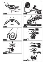
Fig.5:
1.
Lock-off lever
2.
Switch lever
Automatic speed change function
►
Fig.6:
1.
Mode indicator
Mode indicator status
Operation mode
On
Off
High speed mode
High torque mode
This tool has "high speed mode" and "high torque
mode". It automatically changes operation mode
depending on the work load. When mode indicator
lights up during operation, the tool is in high torque
mode.
Accidental re-start preventive
function
Even if installing the battery cartridge while pulling the
switch lever, the tool does not start.
To start the tool, first release the switch lever. Then pull
the lock-off lever, and pull the switch lever.
Electronic torque control function
The tool electronically detects situations where the
wheel or accessory may be at risk to be bound. In the
situation, the tool is automatically shut off to prevent
further rotation of the spindle (it does not prevent
kickback).
To restart the tool, switch off the tool first, remove the
cause of sudden drop in the rotation speed, and then
turn the tool on.
Summary of Contents for DGA701ZU
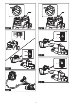
Page 2: ...1 2 3 Fig 1 1 2 Fig 2 1 Fig 3 1 Fig 4 1 2 Fig 5 1 Fig 6 Fig 7 1 2 3 Fig 8 2 ...
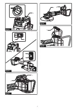
Page 5: ...1 Fig 25 1 Fig 26 2 1 3 4 5 6 7 Fig 27 Fig 28 1 Fig 29 4 3 1 2 Fig 30 1 2 3 Fig 31 5 ...
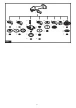
Page 6: ...1 Fig 32 1 2 2 1 Fig 33 Fig 34 1 Fig 35 2 1 Fig 36 1 Fig 37 6 ...
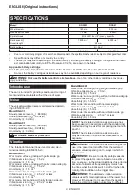
Page 7: ...1 Fig 38 1 2 2 1 Fig 39 1 2 Fig 40 2 1 Fig 41 1 Fig 42 7 ...
Page 8: ...1 8 2 3 5 6 3 13 2 5 4 14 15 16 17 18 12 7 5 10 6 7 19 20 3 5 11 5 8 9 Fig 43 8 ...
Page 131: ...131 ...


