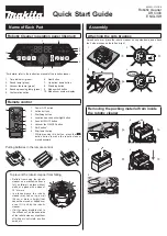


P 8/ 9
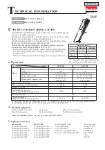
C
ircuit diagram
Fig. D-1
W
iring diagram
Fig. D-2
Housing (L) side
Housing (R) side
red marking indicating plus pole
Switch side (top side)
Connect white Lead wires to the plus terminal of Motor assembly (the terminal indicated by a red marking).
Connect blue Lead wires to the other terminal (the minus terminal) of Motor assembly.
Then assemble Motor section to Housing (L) with the plus terminal of Motor assembly on Switch side (top side).
Note:
Make sure that the wire connecting portion of each receptacle is positioned on Housing (L) side.
[1] Wiring of Motor Assembly
Receptacle
= Wire connecting portion
of Receptacle
COM
AS
NO
Switch
Controller unit
Terminal
Red (200mm)
White (130mm)
Yellow (130mm)
Orange (100mm)
Red marking
DC Motor
Line filter (if used)
Blue (130mm)
Black (150mm)
Motor assembly