background image

P  5/ 9

R

epair

[3] DISASSEMBLY/ASSEMBLY

[3] -2. Motor Section

ASSEMBLING

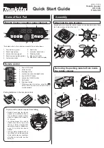
5) Fix Lead wires with Lead wire holder of Housing (L) after connecting them as illustrated in 

Fig. 8

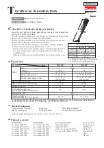
6) Insert Sponge sheet 15-25 to Lead wire holder in order to prevent Lead wires from coming loose. (

Fig. 9

)

Fig. 8

Fig. 9

After connecting Lead wires of Motor assembly

with Controller and Switch, fix the Lead wires

securely by pushing the Lead wires deep into

the slit of Lead wire holder until they stop.

Lead wires of Motor assembly

Lead wire holder

Controller

Housing (L)

Switch

Motor assembly

Sponge sheet 15-25

Folded side

Controller side

After putting these lead wires into the bottom of lead wire holder, 

insert a folded Sponge sheet 15-25 so that the sponge sheet’s height

and the ribs’ height are in a line as illustrated below.

Note:

 Face the folded side to Controller side.   

Summary of Contents for DCL140

Page 1: ...ry BL1830 3 with Battery without T nozzle Extension pipe and Sash nozzle 4 with Battery BL1415 BL1415N 5 with Battery BL1815 BL1815N BL1820 Nozzle assembly for rug carpet Shelf brush Flexible hose Rou...

Page 2: ...ly steps Fig 1 2 Separate Capsule from Housing by pulling it in the direction of the arrow 3 Remove 4x18 Tapping screw and Flat washer 4 Valve can now be disassembled from Capsule 4x18 Tapping screw F...

Page 3: ...f Motor assembly Fan cover 1 Assemble Fan cover to Motor assembly Fig 4 Motor assembly Fig 4 Housing R 3x16 Tapping screw 7 pcs Fig 2 Fig 3 Stay Remove Housing R by unscrewing seven 3x16 Tapping screw...

Page 4: ...ing L as illustrated below Compression spring 4 Switch lever Housing L rib Fig 7 Rubber ring Switch Fan cover Housing L The assembled Rubber ring has to fully cover the Base section of Motor assembly...

Page 5: ...ssembly with Controller and Switch fix the Lead wires securely by pushing the Lead wires deep into the slit of Lead wire holder until they stop Lead wires of Motor assembly Lead wire holder Controller...

Page 6: ...of Housing L notch of Stay Stay 3x16 Tapping screw 7 pcs 1 Remove Sponge sheet 50 50 from the vent frame of Housing R L 2 Remove sponge dust remaining on the pins of the vent frame ASSEMBLING Fig 12 1...

Page 7: ...9 Repair 4 MAINTENANCE Fig 13 When Housing is disassembled clean up the inside of the machine by blowing off the dust that settles on DC Motor Fan Housing etc with air duster for longer tool life Fig...

Page 8: ...the minus terminal of Motor assembly Then assemble Motor section to Housing L with the plus terminal of Motor assembly on Switch side top side Note Make sure that the wire connecting portion of each r...

Page 9: ...Pass Lead wires between Rib and Inner wall of Housing Red marking Controller Housing L side Housing R side Switch Connect Receptacles to Switch terminals with the wire connecting portion of each rece...

Reviews: