background image

W

iring  diagram

7

7

Wiring to DC motor

Wiring in Battery housing

Red  point  mark

Holder pump side

Tank complete side

Battery Housing L

viewing from 

Battery Housing R side

Battery housing L

viewed from Bottom

Connect the Lead wire (red) from
Controller to the Terminal by Red 
point mark which desi pole.

Fig. D-3

Fig. D-4

Receptacle

Lead wire (

red

from Controller

Battery housing L

Fix these Lead wires 
with Lead wire holders.

Fix the Lead wires 
with Lead wire holders.

Controller

These Lead wires have 
to be tightened in this area.

Terminal

Receptacles 
connected to 
Switch

Fuse

Switch

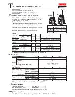
Summary of Contents for BVF104

Page 1: ...also include the accessories listed below in Standard equipment BVF104RF BVF104Z BVF104 BVF154RF BVF154Z BVF154 Model No BL1830 Li ion 3 0Ah DC18RA No No No type quantity Charger 1 No Battery Battery...

Page 2: ...2 1 Pump assembly DC motor DISASSEMBLING M5x10 Screw 4pcs Cushion 1 Remove Cushion from Tank complete by loosening four M5x10 Screws Fig 2 2 Remove Pump holder from Tank complete by loosening three M...

Page 3: ...disassembling step in reverse Note 1 Pass the emboss of Pump assembly through the large hole of Plate 1 2 Align the notch on bottom side of Gear set with Joint of pump assembly to pass the liquid thro...

Page 4: ...Battery housing from Tank complete Fig 14 3 Remove two receptacles from Switch terminals Fig 15 4 Pressing the leaf spring portions of Switch with screwdriver push out Switch to Cover assembly side F...

Page 5: ...attery housing R Fig 17 Fig 18 Fuse Fuse holder Take the disassembling step in reverse 1 Remove Battery housing from Tank complete Fig 14 2 Remove Fuse holder from Battery housing R by picking the nea...

Page 6: ...Switch Fuse Holder pump interferes in wiring to DC motor when the wire connecting portion of Receptacles are faced to Pump holder side Facing the wire connecting portion of Receptacles to the opposit...

Page 7: ...ewed from Bottom Connect the Lead wire red from Controller to the Terminal by Red point mark which designates pole Fig D 3 Fig D 4 Receptacle Lead wire red from Controller Battery housing L Fix these...

Reviews: