background image

5

ENGLISH 

(Original instructions)

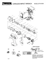
Explanation of general view 

1

Switch trigger 

2

Outer sleeve 

3

Screw 

4

Inner sleeve 

5

Pin 

6

Tip rod 

7

Tip rod spring 

8

Inner sleeve spring 

9

There should be no gap 
between the outer sleeve and 
the tool. 

10 Bolt tip 
11 Nut 
12 Notched portion 
13 Tip ejector (Tip lever) 
14 Identification mark 

15

Bolt 

16

Chamfered 

17

Washer

18

Remaining length 

19

Limit mark 

20

Screwdriver 

21

Brush holder cap 

22

Protector 

SPECIFICATIONS 

Model

6922NB

Bolt size ................................................... M16, M20, M22
Max. normal torque ......................................... 803.6 N•m
No load speed (min

–1

) .................................................. 20

Dimensions (L × W × H) ......249 mm × 84 mm × 252 mm
Net weight .............................................................. 4.8 kg 
Safety class  ...........................................................  

/II

• Due to our continuing program of research and devel-

opment, the specifications herein are subject to change
without notice. 

• Specifications may differ from country to country.
• Weight according to EPTA-Procedure 01/2003 

ENE038-1

Intended use 

The tool is intended for fastening “tor-shear type” high
tensile bolts. 

ENF002-2

Power supply 

The tool should be connected only to a power supply of
the same voltage as indicated on the nameplate, and can
only be operated on single-phase AC supply. They are
double-insulated and can, therefore, also be used from
sockets without earth wire. 

GEA010-1

General Power Tool Safety Warnings

WARNING Read all safety warnings and all

instructions. 

Failure to follow the warnings and

instructions may result in electric shock, fire and/or
serious injury.

Save all warnings and instructions for future refer-
ence.

GEB006-6

SHEAR WRENCH SAFETY RULES

1.

Hold power tool by insulated gripping surfaces,
when performing an operation where the fas-
tener may contact hidden wiring or its own cord.

Fasteners contacting a “live” wire may make
exposed metal parts of the power tool “live” and
could give the operator an electric shock.

2.

Always be sure you maintain good balance and
firm footing. 
Be sure no one is below when using the tool in
high or elevated locations. 

3.

Hold the tool firmly. 

4.

Use care and common sense when disposing of
sheared bolt tips. Falling tips from high loca-
tions or scattered tips can cause severe injury.  

SAVE THESE INSTRUCTIONS.

WARNING:
DO NOT let comfort or familiarity with product
(gained from repeated use) replace strict adherence
to shear wrench safety rules for the subject product.
MISUSE or failure to follow the safety rules stated in
this instruction manual may cause serious personal
injury.

FUNCTIONAL DESCRIPTION 

CAUTION: 

• Always be sure that the tool is switched off and

unplugged before adjusting or checking function on the
tool. 

Switch action (Fig. 1) 

CAUTION: 

• Before plugging in the tool, always check to see that

the switch trigger actuates properly and returns to the
“OFF” position when released. 

To start the tool, simply pull the switch trigger. Release
the switch trigger to stop. 

ASSEMBLY 

CAUTION: 

• Always be sure that the tool is switched off and

unplugged before carrying out any work on the tool. 

Removing the outer and inner sleeves 

CAUTION: 

• Be careful not to allow foreign matter to enter the

insides of the tool when removing or installing the outer
and inner sleeves. 

If you need, for your work, different sizes of outer sleeve
and inner sleeve from those installed on your tool,
replace the sleeves as follows. 
Loosen the two screws while holding the outer sleeve.
The outer and inner sleeves will be pushed up by the
springs built into the tool. 

(Fig. 2)


Press the pin down to remove the inner sleeve from the
outer sleeve. Be careful not to drop the inner sleeve
when removing it. Do not remove the inner sleeve spring,
tip rod and tip rod spring from the tool. 

(Fig. 3 & 4)


Summary of Contents for 6922NB

Page 1: ...tructions D Shear Schrauber Betriebsanleitung I Avvita bullone Istruzioni per l uso NL Slagmoersleutel voor breekmoeren Gebruiksaanwijzing E Llave de torsión Manual de instrucciones P Cisalha Manual de instruções DK Shear nøgle Brugsanvisning GR Ηλεκτρικ κλειδί Οδηγίες χρήσεως 6922NB ...

Page 2: ...2 1 2 3 4 5 6 3 2 9 2 5 4 6 8 7 4 2 5 2 3 1 004983 004987 004988 004984 004986 004985 ...

Page 3: ...3 7 8 9 10 11 12 13 14 11 15 16 17 14 13 10 2 12 10 2 11 4 10 004989 004994 004993 005848 007539 004990 004992 004991 18 ...

Page 4: ...4 15 16 20 21 22 001145 004995 19 ...

Page 5: ... exposed metal parts of the power tool live and could give the operator an electric shock 2 Always be sure you maintain good balance and firm footing Be sure no one is below when using the tool in high or elevated locations 3 Hold the tool firmly 4 Use care and common sense when disposing of sheared bolt tips Falling tips from high loca tions or scattered tips can cause severe injury SAVE THESE IN...

Page 6: ...erously below Keep the tips off of the ground floor walkways etc to prevent injury from tripping or fall ing Fig 11 12 CAUTION Washer and nut have head and tail Head has identifi cation mark for nut and chamfer for washer When plac ing them be careful not to place in reverse Replace nut bolt and washer all together at one time when these rotate together nut rotates excessively or a bolt protrude f...

Page 7: ...ual use of the power tool can differ from the declared emission value depending on the ways in which the tool is used Be sure to identify safety measures to protect the oper ator that are based on an estimation of exposure in the actual conditions of use taking account of all parts of the operating cycle such as the times when the tool is switched off and when it is running idle in addition to the...

Page 8: ...spectées Conservez toutes les mises en garde et instructions pour référence ultérieure GEB006 6 CONSIGNES DE SÉCURITÉ DE LA BOULONNEUSE 1 Saisissez l outil électrique par ses surfaces de poigne isolées lorsque vous effectuez une opé ration au cours de laquelle la visseuse peut entrer en contact avec des fils cachés ou avec son propre cordon d alimentation Le contact avec un fil sous tension mettra...

Page 9: ...on intérieur Fig 9 Relâchez la gâchette et retirez l outil en ligne droite Fig 10 ATTENTION N appliquez pas une force excessive vers le bas sur l outil N appliquez vers le bas que la force nécessaire pour tenir l outil fermement Tirez sur l éjecteur de bout levier de retrait de bout pour éjecter de l outil le bout de boulon Attrapez les bouts de boulon coupés pour éviter qu ils ne tombent dangereu...

Page 10: ...l de l outil électrique peut être différente de la valeur d émission déclarée suivant la façon dont l outil est utilisé Les mesures de sécurité à prendre pour protéger l utili sateur doivent être basées sur une estimation de l exposition dans des conditions réelles d utilisation en tenant compte de toutes les composantes du cycle d utilisation comme par exemple le moment de sa mise hors tension lo...

Page 11: ...ie die Maschine nur an den isolierten Griffflächen wenn Sie Arbeiten ausführen bei denen die Gefahr besteht dass das Befesti gungselement verborgene Kabel oder das eigene Kabel kontaktiert Bei Kontakt mit einem Strom führenden Kabel können die freiliegenden Metallteile der Maschine ebenfalls Strom führend werden so dass der Benutzer einen elektrischen Schlag erleiden kann 2 Achten Sie stets auf gu...

Page 12: ...ie das Werkzeug geradlinig ab Abb 10 VORSICHT Üben Sie keinen übermäßigen Druck auf die Maschine aus Üben Sie nur so viel Druck aus dass die Maschine sicher gehalten wird Betätigen Sie den Spitzenauswerfer Spitzenhebel um die Schraubenspitze aus dem Werkzeug auszuwerfen Fangen Sie die abgescherten Schraubenspitzen auf um gefährliches Herunterfallen zu verhüten Sammeln Sie die Schraubenspitzen von ...

Page 13: ...nge zogen werden Der angegebene Vibrationsemissionswert kann auch für eine Vorbewertung des Gefährdungsgrads verwen det werden WARNUNG Die Vibrationsemission während der tatsächlichen Benutzung des Elektrowerkzeugs kann je nach der Benutzungsweise der Maschine vom angegebenen Emissionswert abweichen Identifizieren Sie Sicherheitsmaßnahmen zum Schutz des Benutzers anhand einer Schätzung des Gefähr ...

Page 14: ... superfici isolate quando si esegue una operazione in cui i dispositivi di chiusura potrebbero fare contatto con fili elet trici nascosti o con il suo cavo di alimentazione I dispositivi di chiusura che fanno contatto con un filo elettrico sotto tensione potrebbero mettere sotto tensione le parti metalliche esposte dell utensile dando una scossa all operatore 2 Mantenere sempre un buon equilibrio ...

Page 15: ...rso il basso necessario per mantenere fermo l utensile Tirare l espulsore punta leva punta per espellere la punta del bullone dall utensile Evitare il pericolo che le punte dei bulloni tagliate cadano prendendole Le punte non devono essere lasciate sul terreno pavimento pas saggio ecc perché c è pericolo di lesioni se vi si inciampa sopra o si cade Figg 11 e 12 ATTENZIONE Le rondelle e i dadi hann...

Page 16: ...utensile elettrico può differire dal valore di emis sione dichiarato a seconda dei modi in cui viene usato l utensile Identificare le misure di sicurezza per la protezione dell operatore basate sulla stima dell esposizione nelle condizioni reali d utilizzo tenendo presente tutte le parti del ciclo operativo come le volte in cui l utensile viene spento e quando gira a vuoto oltre al tempo di funzio...

Page 17: ...om in de toekomst te kunnen raadplegen GEB006 6 VEILIGHEIDSVOORSCHRIFTEN VOOR DE SLAGMOERSLEUTEL 1 Houd elektrisch gereedschap vast bij het geïso leerde oppervlak van de handgrepen wanneer u werkt op plaatsen waar het bevestigingsmateri aal in aanraking kan komen met verborgen bedrading of zijn eigen netkabel Wanneer beves tigingsmaterialen in aanraking komen met onder spanning staande draden zull...

Page 18: ... afgedraaid ter plaatse van de groef De bout punt blijft achter in de binnenste bus Fig 9 Laat de trekkerschakelaar los en haal het gereedschap in een rechte lijn naar achteren Fig 10 LET OP Duw het gereedschap niet al te krachtig aan Er is niet meer druk nodig dan alleen die vereist om het gereed schap stevig vast te houden Bedien de boutpunt uitwerphendel om de boutpunt uit het gereedschap te we...

Page 19: ...ewaarde kan ook worden gebruikt voor een beoordeling vooraf van de blootstell ing WAARSCHUWING De trillingsemissie tijdens het gebruik van het elektrisch gereedschap in de praktijk kan verschillen van de opgegeven trillingsemissiewaarde afhankelijk van de manier waarop het gereedschap wordt gebruikt Zorg ervoor dat veiligheidsmaatregelen worden getrof fen ter bescherming van de operator die zijn g...

Page 20: ...una descarga eléctrica un incendio y o heridas graves Guarde todas las advertencias e instrucciones para futuras referencias GEB006 6 NORMAS DE SEGURIDAD PARA LA LLAVE DE TORSIÓN 1 Cuando realice una operación en la que el ator nillador pueda entrar en contacto con cableado oculto o con su propio cable sujete la herra mienta eléctrica por las superficies de asimiento aisladas El contacto del atorn...

Page 21: ... gatillo interruptor El manguito exterior girará para comenzar a apretar la tuerca Cuando se obtenga el par de torsión especificado la punta del perno será cizallada por su parte hendida La punta del perno permanecerá dentro del manguito inte rior Fig 9 Suelte el gatillo interruptor y retire la herramienta en línea recta Fig 10 PRECAUCIÓN No fuerce la herramienta hacia abajo excesivamente Aplique ...

Page 22: ...tilizar para comparar una herramienta con otra El valor de emisión de vibración declarado también se puede utilizar en una valoración preliminar de exposi ción ADVERTENCIA La emisión de vibración durante la utilización real de la herramienta eléctrica puede variar del valor de emisión declarado dependiendo de las formas en las que la herramienta sea utilizada Asegúrese de identificar medidas de se...

Page 23: ...ções para futuras referências GEB006 6 AVISOS DE SEGURANÇA PARA A CISALHA 1 Agarre na ferramenta eléctrica pelas partes iso ladas quando executa uma operação em que o parafuso possa entrar em contacto com fios ocultos ou com o seu próprio fio O contacto do parafuso com um fio ligado poderá carregar as partes metálicas da ferramenta e causar choque eléctrico no operador 2 Certifique se sempre de qu...

Page 24: ...te para manter firme a ferra menta Empurre o ejector da ponta alavanca da ponta para retirar a ponta do perno da ferramenta Agarre nas pon tas dos pernos partidas para evitar que caiem perigosa mente para baixo Retire as do chão passeios etc para evitar danos quando cairem Fig 11 e 12 PRECAUÇÃO A arruela e a porca têm cabeça e cauda A cabeça tem uma marca para a porca e chanfradura para a arruela ...

Page 25: ...te a utilização real da fer ramenta eléctrica pode diferir do valor de emissão indi cado dependendo das formas como a ferramenta é utilizada Certifique se de identificar as medidas de segurança para protecção do operador que sejam baseadas em uma estimativa de exposição em condições reais de utilização considerando todas as partes do ciclo de operação tal como quando a ferramenta está desli gada e...

Page 26: ...en strømførende ledning kan gøre uafdækkede metaldele på maskinen strømførende og give operatøren stød 2 Sørg altid for at holde en god balance og et godt fodfæste Kontroller at der ikke befinder sig nogen personer nedenunder når De arbejder med maskinen på høje eller hævede steder 3 Hold godt fast i maskinen 4 Udvis omhu og sund fornuft når De bortskaffer afklippede boltspidser Spidser der falder...

Page 27: ...r at få boltspid sen ud af maskinen Opfang de afklippede boltspidser så de ikke falder ned og derved udgør en fare Hold spid serne borte fra jorden gulvet løbebroer og lignende således at personskade forårsaget af snublen eller fald undgås Fig 11 og 12 FORSIGTIG Spændeskiven og møtrikken har hoved og hale Hove det har en identifikationsafmærkning for møtrik og fas for spændeskive Vær påpasselig me...

Page 28: ...endelse af maskinen kan være forskellig fra den erklærede emissi onsværdi afhængigt af den måde hvorpå maskinen anvendes Sørg for at identificere de sikkerhedsforskrifter til beskyttelse af operatøren som er baseret på en vurde ring af eksponering under de faktiske brugsforhold med hensyntagen til alle dele i brugscyklen som f eks de gange hvor maskinen er slukket og når den kører i tomgang i tilg...

Page 29: ...αλείο ΠΡΟΕΙΔΟΠΟΙΗΣΗ Διαβάστε λες τις προειδοποιήσεις ασφαλείας και λες τις οδηγίες Η μη τήρηση των προειδοποιήσεων και οδηγιών ενδέχεται να καταλήξει σε ηλεκτροπληξία πυρκαγιά ή και σοβαρ τραυματισμ Φυλάξτε λες τις προειδοποιήσεις και τις οδηγίες για μελλοντική παραπομπή GEB006 6 ΚΑΝΟΝΕΣ ΑΣΦΑΛΕΙΑΣ ΗΛΕΚΤΡΙΚΟΥ ΚΛΕΙΔΙΟΥ 1 Να κρατάτε το ηλεκτρικ εργαλείο απ τις λαβές με μ νωση ταν εκτελείτε εργασίες κ...

Page 30: ...πουλονιού Εάν το άκρο χτυπηθεί μπορεί να πάθει ζημιά έτσι ώστε να μην εφαρμ ζει πλέον μέσα στο μανίκι κατάλληλα Αρχικά σφίξτε τα μπουλ νια προκαταρκτικά χρησιμοποιώντας ένα κλειδί χειρ ς και στη συνέχεια σφίξτε τα με αυτ το εργαλείο Χρησιμοποιήστε αυτ το εργαλείο μ νο μετά το προκαταρκτικ σφίξιμο χωρίς να ξεκινήσετε το σφίξιμο με αυτ το εργαλείο Διατηρείτε εμπρ σθια πίεση στο εργαλείο ενώ το σύρετ...

Page 31: ...ντοτε ανταλλακτικών Μάκιτα ΠΡΟΑΙΡΕΤΙΚΑ ΕΞΑΡΤΗΜΑΤΑ ΠΡΟΣΟΧΗ Αυτά τα εξαρτήματα ή προσαρτήματα συνιστώνται για χρήση με το εργαλείο Μάκιτα που περιγράφτηκε στις οδηγίες αυτές Η χρήση οτιδήποτε άλλων εξαρτημάτων ή προσαρτημάτων μπορεί να προκαλέσει κίνδυνο τραυματισμού σε άτομα Χρησιμοποιείτε τα εξαρτήματα ή προσαρτήματα μ νο για την χρήση που προορίζονται Εάν χρειάζεστε οποιαδήποτε βοήθεια για περισσ...

Page 32: ...ψη λες τις συνιστώσες του κύκλου λειτουργίας πως τους χρ νους που το εργαλείο είναι εκτ ς λειτουργίας και ταν βρίσκεται σε αδρανή λειτουργία πέραν του χρ νου ενεργοποίησης ENH101 15 Μ νο για χώρες της Ευρώπης Δήλωση Συμμ ρφωσης ΕΚ Η Makita Corporation ως ο υπεύθυνος κατασκευαστής δηλώνει τι το τα ακ λουθο α μηχάνημα τα της Makita Χαρακτηρισμ ς μηχανήματος Ηλεκτρικ κλειδί Αρ μοντέλου Τύπος 6922NB ε...

Reviews: