


R
epair P 5 / 11
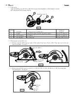
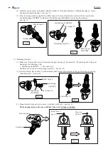
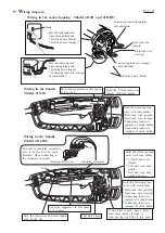
< 5 > Disassembling clutch section
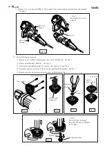
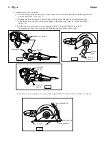
< 6 > Assembling clutch section
Fig. 11
Fig. 12
Fig. 14A
Fig. 14B
Fig. 14C
Fig. 14D
( 1 ) For removing clutch section from bearing box, take the step of Fig. 2, Fig.3, Fig.4 and Fig. 5 at page 3.
( 1 ) Apply MAKITA grease SG. No.0 to the lock spring 24.
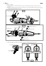
( 3 ) Lock sleeve can be mounted to the spiral bevel gear 48 in the same way as the lock spring 24.
See Fig. 14A,B,C and D.
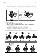
( 2 ) First, put the lock spring 24 slantingly on the spiral bevel gear 48. And press, such as, the portion A
of lock spring 24 See Fig. 13A
Second, turn the spiral bevel gear 48, and press the portion D. See Fig. 13B
Thirdly, turn the spiral bevel gear 48, and press the portion C. See Fig. 13C
Fourthly, turn the spiral bevel gear 48, and press the portion B. See Fig. 13D.
And finally, press the lock spring 24 into the spiral bevel gear 48 completely. See Fig. 13E.
( 2 ) Turning lock sleeve clockwise, pull the spiral bevel gear 48. So lock sleeve can be separated from the spiral
bevel gear 48. See Fig. 11.
( 3 ) Turning the lock spring 24 clockwise, pull the spiral bevel gear 48. So lock spring 24 can be separated
from the spiral bevel gear 48. See Fig. 12.
Water plier
Spiral bevel gear 48
Lock
sleeve
Spiral bevel gear 48
Water plier
Lock
spring 24
Soft cloth
< Note >
Cover the lock spring 24 with soft cloth to protect from
the damage as per this illustration.
A
C
D
B
C
D
A
B
C
A
B
D
B
A
D
C
Spiral bevel
gear 48
Lock spring 24
Lock
sleeve
Lock
spring 24
Fig. 13A
Fig. 13B
Fig. 13C
Fig. 13D
Fig. 13E
Arbor press
Arbor press
Spiral bevel
gear 48


