


W
iring diagram P 11 / 11
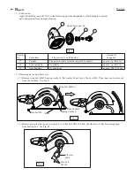
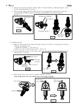
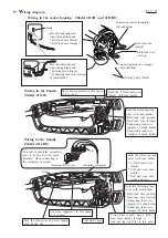
Wiring in the motor housing (Model 4112H and 4112HS)
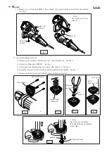
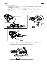
Wiring in the handle
(Model 4112H)
Wiring in the handle
(Model 4112HS)
Pass the following lead
wires through the hook.
* Field lead wire (black)
* Field lead wire (orange)
Pass the following lead
wires through the hook.
* Field lead wire (black)
* Connecting lead wire (orange)
of brush holder
Hook
Hook
Connecting lead wire (purple)
of brush holder
Field lead wire
(purple)
Field lead wire
(orange)
Connecting lead wire (orange)
of brush holder
Field lead wire (black)
Hold the following lead
wires with lead holder.
*Field lead wire (purple)
*Field lead wire (orange)
*Connecting lead wire
(purple) of brush holder
*Connecting lead wire
(orange) of brush holder
Hold the following lead
wires with lead holder.
*Field lead wire (purple)
*Field lead wire (orange)
*Connecting lead wire
(purple) of brush holder
*Connecting lead wire
(orange) of brush holder
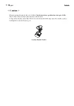
Hold the 2 field lead wires
(black) with lead holder.
Hold the following lead
wires with lead holder.
* 2 Field lead wires
(black)
* Soft start lead wire
(white)
* Soft start lead wire
(orange of red)
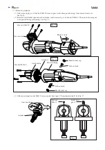
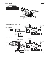
Put noise suppressor in this space,
if it is used.
Put noise suppressor in this space,
if it is used.
If line filter is used, pass 2 field
lead wires (black) through it.
And put the line filter in this place.
Pass the lead wires of power supply
cord by the rib.
Rib
Insulated receptacle
Terminal of switch
Slit
The slits of insulated receptacles
have to be faced to the same
direction, when connecting to
the terminals of switch.
Soft start circuit


