

6
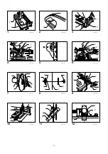
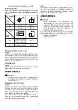
Interval between vise and guide plate
Fig.4
The original spacing or interval between the vise and the
guide plate is 0 - 170 mm. If your work requires wider
spacing or interval, proceed as follows to change the
spacing or interval.
Remove the two hex bolts which secure the guide plate.
Move the guide plate as shown in the figure and secure
it using the hex bolts. The following interval settings are
possible:
35 - 205 mm
70 - 240 mm
Fig.5
CAUTION:
•
Remember that narrow workpieces may not be
secured safely when using the two, wider interval
settings.
Setting for desired cutting angle
Fig.6
To change the cutting angle, loosen the two hex bolts
which secure the guide plate. Move the guide plate to
the desired angle (0° - 45°) and tighten the hex bolts
securely.
CAUTION:
•
Never perform miter cuts when the guide plate is
set at the 35 - 205 mm or 70 - 240 mm position.
ASSEMBLY
CAUTION:
•
Always be sure that the tool is switched off and
unplugged before carrying out any work on the
tool.
Removing or installing cut-off wheel
Fig.7
To remove the wheel, raise the safety guard. Press the
shaft lock so that the wheel cannot revolve and use the
socket wrench to loosen the hex bolt by turning it
counterclockwise. Then remove the hex bolt, outer
flange and wheel. (Note: Do not remove the inner flange,
ring and O-ring.)
To install the wheel, follow the removal procedures in
reverse.
Fig.8
CAUTION:
•
Be sure to tighten the hex bolt securely. Insufficient
tightening of the hex bolt may result in severe injury.
Use the socket wrench provided to help assure
proper tightening.
•
Always use only the proper inner and outer flanges
which are provided with this tool.
•
Always lower the safety guard after replacing the
wheel.
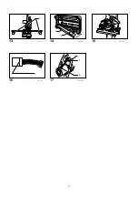
Securing workpiece
Fig.9
By turning the vise handle counterclockwise and then
flipping the vise nut to the left, the vise is released from
the shaft threads and can be moved rapidly in and out.
To grip workpieces, push the vise handle until the vise
plate contacts the workpiece. Flip the vise nut to the right
and then turn the vise handle clockwise to securely
retain the workpiece.
CAUTION:
•
Always set the vise nut to the right fully when
securing the workpiece. Failure to do so may result
in insufficient securing of the workpiece. This could
cause the workpiece to be ejected or cause a
dangerous breakage of the wheel.
When the cut-off wheel has worn down considerably,
use a spacer block of sturdy, non-flammable material
behind the workpiece as shown in the figure. You can
more efficiently utilize the worn wheel by using the mid
point on the periphery of the wheel to cut the workpiece.
Fig.10
When cutting workpieces over 65 mm wide at an angle,
attach a straight piece of wood (spacer) over 190 mm
long x 45 mm wide to the guide plate as shown in the
figure. Attach this spacer with screws through the holes
in the guide plate.
Fig.11
If you use a spacer block which is slightly narrower than
the workpiece as shown in the figure, you can also utilize
the wheel economically.
Fig.12
Long workpieces must be supported by blocks of
non-flammable material on either side so that it will be
level with the base top.
Fig.13
OPERATION
Hold the handle firmly. Switch on the tool and wait until
the wheel attains full speed before lowering gently into
the cut. When the wheel contacts the workpiece,
gradually bear down on the handle to perform the cut.
When the cut is completed, switch off the tool and WAIT
UNTIL THE WHEEL HAS COME TO A COMPLETE
STOP before returning the handle to the fully elevated
position.
CAUTION:
•
Proper handle pressure during cutting and
maximum cutting efficiency can be determined by
the amount of sparks that is produced while cutting.
Your pressure on the handle should be adjusted to
produce the maximum amount of sparks. Do not
force the cut by applying excessive pressure on
the handle. Reduced cutting efficiency, premature
wheel wear, as well as, possible damage to the
Summary of Contents for 2414NB
Page 3: ...3 1 13 003767 1 2 14 005272 15 003768 1 16 001145 1 2 17 003769...
Page 10: ...10 Fig 1 Fig 2 Fig 3 Fig 4 0 170 35 205 70 240 Fig 5 Fig 6 0 45 35 205 70 240 Fig 7 Fig 8...
Page 12: ...12 Fig 16 Fig 17 17...
Page 39: ...39...
Page 40: ...40 Makita Corporation Anjo Aichi Japan 884151A853...


