

5
The technical documentation is kept by our authorised
representative in Europe who is:
Makita International Europe Ltd,
Michigan, Drive, Tongwell,
Milton Keynes, MK15 8JD, England
30th January 2009
000230
Tomoyasu Kato
Director
Makita Corporation
3-11-8, Sumiyoshi-cho,
Anjo, Aichi, JAPAN
ENB066-1
ADDITIONAL SAFETY RULES
FOR TOOL
1.
Wear protective glasses. Also wear hearing
protection during extended periods of
operation.
2.
Use only wheels recommended by the
manufacturer which have a maximum
operating speed at least as high as "No Load
RPM" marked on the tool’s nameplate. Use
only fiberglass-reinforced cut-off wheels.
3.
Check the wheel carefully for cracks or
damage before operation. Replace cracked or
damaged wheel immediately.
4.
Secure the wheel carefully.
5.
Use only flanges specified for this tool.
6.
Be careful not to damage the spindle, flanges
(especially the installing surface) or bolt, or
the wheel itself might break.
7.
KEEP GUARDS IN PLACE and in working
order.
8.
Hold the handle firmly.
9.
Keep hands away from rotating parts.
10.
Make sure the wheel is not contacting the
work-piece before the switch is turned on.
11.
Before using the tool on an actual workpiece,
let it simply run for several minutes first.
Watch for flutter or excessive vibration that
might be caused by poor installation or a
poorly balanced wheel.
12.
Watch out for flying sparks when operating.
They can cause injury or ignite combustible
materials.
13.
Remove material or debris from the area that
might be ignited by sparks. Be sure that others
are not in the path of the sparks. Keep a proper,
charged fire extinguisher closely available.
14.
Use the cutting edge of the wheel only. Never
use side surface.
15.
If the wheel stops during the operation, makes
an odd noise or begins to vibrate, switch off
the tool immediately.
16.
Always switch off and wait for the wheel to
come to a complete stop before removing,
securing workpiece, working vise, changing
work position, angle or the wheel itself.
17.
Do not touch the workpiece immediately after
operation; it is extremely hot and could burn
your skin.
18.
Store wheels in a dry location only.
SAVE THESE INSTRUCTIONS.
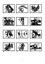
INSTALLATION
Securing cut-off
Fig.1
This tool should be bolted with two bolts to a level and
stable surface using the bolt holes provided in the tool's
base. This will help prevent tipping and possible
personal injury.
FUNCTIONAL DESCRIPTION
CAUTION:
•
Always be sure that the tool is switched off and
unplugged before adjusting or checking function on
the tool.
Switch action
Fig.2
CAUTION:
•
Before plugging in the tool, always check to see
that the switch trigger actuates properly and
returns to the "OFF" position when released.
For tool with lock button
To start the tool, simply pull the switch trigger. Release
the switch trigger to stop. For continuous operation, pull
the switch trigger and then push in the lock button. To
stop the tool from the locked position, pull the switch
trigger fully, then release it.
For tool with lock-off button
To prevent the switch trigger from being accidentally
pulled, a lock-off button is provided.
To start the tool, depress the lock-off button and pull the
switch trigger. Release the switch trigger to stop.
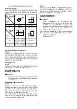
Spark guard
Fig.3
The spark guard is factory-installed with its lower edge
contacting the base. Operating the tool in this position
will cause many sparks to fly around. Loosen the screw
and adjust the spark guard to a position at which
minimum sparks will fly around.
Summary of Contents for 2414NB
Page 3: ...3 1 13 003767 1 2 14 005272 15 003768 1 16 001145 1 2 17 003769...
Page 10: ...10 Fig 1 Fig 2 Fig 3 Fig 4 0 170 35 205 70 240 Fig 5 Fig 6 0 45 35 205 70 240 Fig 7 Fig 8...
Page 12: ...12 Fig 16 Fig 17 17...
Page 39: ...39...
Page 40: ...40 Makita Corporation Anjo Aichi Japan 884151A853...


